Lexmark 782n IPDS Emulation User’s Guide - Page 53
Offset Stacking, 5.1.1 AS/400 and iSeries Offset Stacking
 |
UPC - 734646143080
View all Lexmark 782n manuals
Add to My Manuals
Save this manual to your list of manuals |
Page 53 highlights
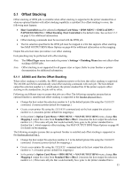
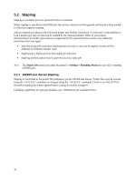
5.1 Offset Stacking Offset stacking of IPDS jobs is available when offset stacking is supported in the printer standard bin or when an optional finisher with offset stacking capability is installed. For offset stacking to occur, the following must happen: • Host Controlled must be selected in Option Card Menu > IPDS MENU > EMULATION > PAPER HANDLING > Offset Stacking. Host Controlled is the default value. See section 3.5.2 on page 33 for additional information. • Offset stacking commands must be received with the IPDS job. • The bin selection specified in the IPDS job must be mapped to a bin that supports offset stacking. See MAP OUTPUT BINS Menu Options on page 40 for additional information on bin mapping. Output bin selection takes precedence over offset stacking. Hole punching may be performed with offset stacking. Note: The Offset Pages menu item under the printer's Settings > Finishing Menu does not affect offset stacking of IPDS jobs. Note: Offset stacking is not supported for all papers sizes or types. Refer to your finisher or printer documentation for additional information. 5.1.1 AS/400 and iSeries Offset Stacking When offset stacking is available, the IPDS emulation reports to the host that offset stacking is supported. The AS/400 and iSeries automatically send offset stacking commands with each job. The host default output bin selection number is 1, which selects the printer standard bin. If the printer supports offset stacking in the standard bin, the job will be offset. Following are different ways to ensure that jobs are offset. The following examples assume that an optional finisher is installed and offset stacking is supported in the finisher physical bin 1. • Change the host output bin selection number to 2 in the default printer file using the CHGPRTF command. (Assumes printer default bin mappings.) • Create a new printer file using the CRTPRTF command and set the host output bin selection number to 2. (Assumes printer default bin mappings.) • In the printer's Option Card Menu > IPDS MENU > MAP OUTPUT BINS menu, change Bin Mapping 1 output bin value from Standard Bin to Bin 1. (Assumes the host output bin selection number is 1.) This routes all jobs that would normally have gone to the printer standard bin to finisher bin 1, which supports offset stacking. See MAP OUTPUT BINS Menu Options on page 40 for details on bin mapping. The following examples assume that an optional finisher is installed and offset stacking is supported in the finisher physical bin 2. • Change the host output bin selection number to 3 in the default printer file using the CHGPRTF command. (Assumes printer default bin mappings.) • Create a new printer file using the CRTPRTF command and set the host output bin selection number to 3. (Assumes printer default bin mappings.) • In the printer's Option Card Menu > IPDS MENU > MAP OUTPUT BINS menu, change Bin Mapping 1 output bin value from Standard Bin to Bin 2. (Assumes the host output bin selection number is 1.) This routes all jobs that would normally have gone to the printer standard bin to 53
-
 1
1 -
2
-
3
-
4
-
5
-
6
-
7
-
8
-
9
-
10
-
11
-
12
-
13
-
14
-
15
-
16
-
17
-
18
-
19
-
20
-
21
-
22
-
23
-
24
-
25
-
26
-
27
-
28
-
29
-
30
-
31
-
32
-
33
-
34
-
35
-
36
-
37
-
38
-
39
-
40
-
41
-
42
-
43
-
44
-
45
-
46
-
47
-
 48
48 -
 49
49 -
 50
50 -
 51
51 -
 52
52 -
 53
53 -
 54
54 -
 55
55 -
 56
56 -
 57
57 -
 58
58 -
59
-
60
-
61
-
62
-
63
-
64
-
65
-
66
-
67
-
68
-
69
-
70
-
71
-
72
-
73
-
74
-
75
-
76
-
77
-
78
-
79
-
80
-
81
-
82
-
83
-
84
-
85
-
86
-
87
-
88
-
89
-
90
-
91
-
92
-
93
-
94
-
95
-
96
-
97
-
98
-
99
-
100
-
101
-
102
-
103
-
104
-
105
-
106
-
107
-
108
-
109
-
110
-
111
-
112
-
113
-
114
-
115
-
116
-
117
-
118
-
119
-
120
-
121
-
122
-
123
-
124
-
125
-
126
-
127
-
128
-
129
 |
 |
