Lexmark X502n Service Manual - Page 179
High voltage power supply (HVPS) removal, System board cage removal
 |
View all Lexmark X502n manuals
Add to My Manuals
Save this manual to your list of manuals |
Page 179 highlights
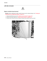
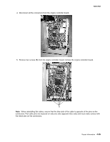
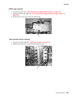
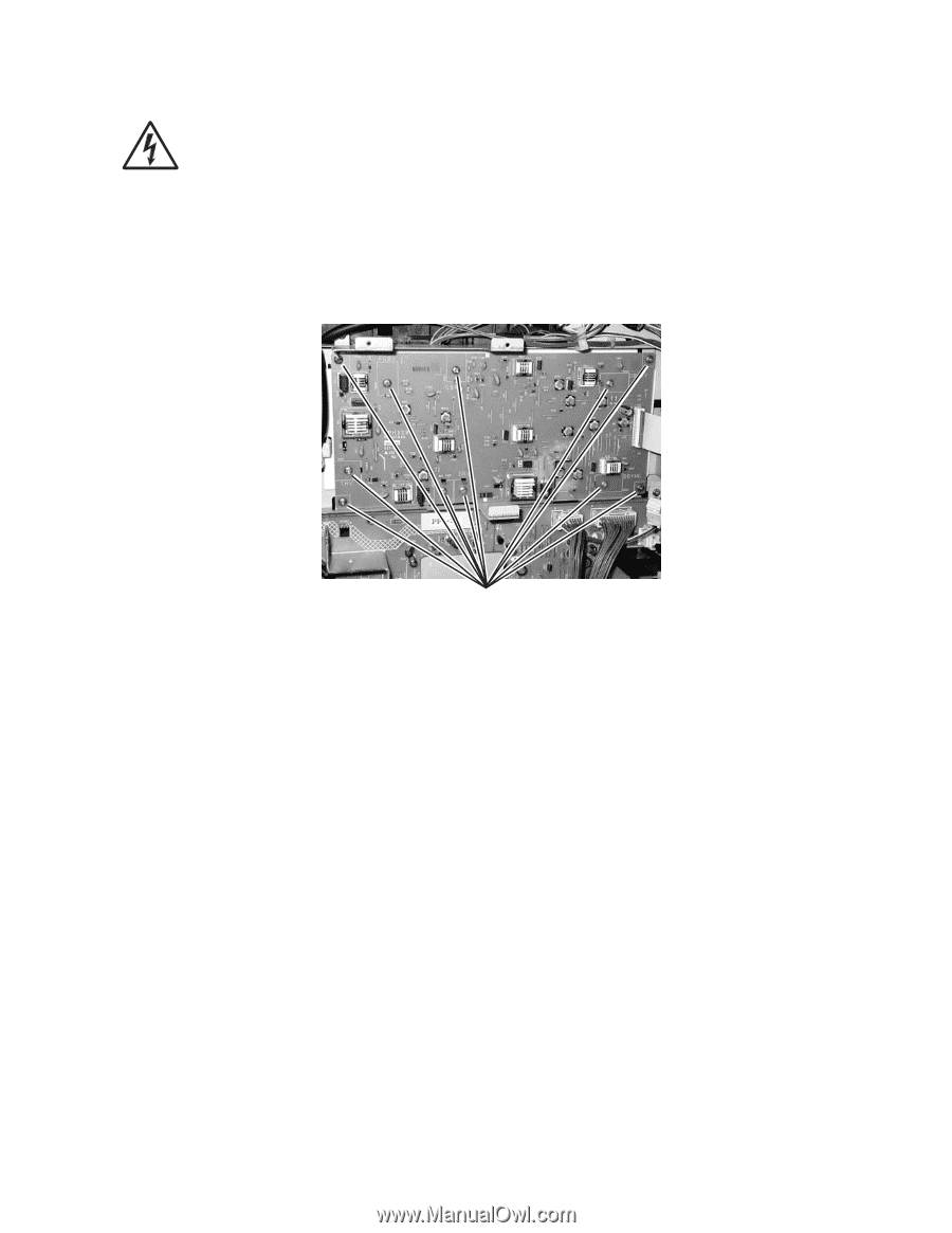
7100-XXX High voltage power supply (HVPS) removal 1.Remove the RIP board cage. See "System board cage removal" on page 4-38. 2.Disconnect all the connectors from the HVPS. Note: When reinstalling flat cables, ensure that the blue side of the cable is opposite of the pins on the connectors. Flat cable pins are exposed on only one side (opposite blue side) and must make contact with the metal pins on the connectors. 3. Remove 11 screws (A) (4 corner screws are gold in color (metal); inner screws are silver (plastic)); remove HVPS. A Repair information 4-39
-
 1
1 -
2
-
3
-
4
-
5
-
6
-
7
-
8
-
9
-
10
-
11
-
12
-
13
-
14
-
15
-
16
-
17
-
18
-
19
-
20
-
21
-
22
-
23
-
24
-
25
-
26
-
27
-
28
-
29
-
30
-
31
-
32
-
33
-
34
-
35
-
36
-
37
-
38
-
39
-
40
-
41
-
42
-
43
-
44
-
45
-
46
-
47
-
48
-
49
-
50
-
51
-
52
-
53
-
54
-
55
-
56
-
57
-
58
-
59
-
60
-
61
-
62
-
63
-
64
-
65
-
66
-
67
-
68
-
69
-
70
-
71
-
72
-
73
-
74
-
75
-
76
-
77
-
78
-
79
-
80
-
81
-
82
-
83
-
84
-
85
-
86
-
87
-
88
-
89
-
90
-
91
-
92
-
93
-
94
-
95
-
96
-
97
-
98
-
99
-
100
-
101
-
102
-
103
-
104
-
105
-
106
-
107
-
108
-
109
-
110
-
111
-
112
-
113
-
114
-
115
-
116
-
117
-
118
-
119
-
120
-
121
-
122
-
123
-
124
-
125
-
126
-
127
-
128
-
129
-
130
-
131
-
132
-
133
-
134
-
135
-
136
-
137
-
138
-
139
-
140
-
141
-
142
-
143
-
144
-
145
-
146
-
147
-
148
-
149
-
150
-
151
-
152
-
153
-
154
-
155
-
156
-
157
-
158
-
159
-
160
-
161
-
162
-
163
-
164
-
165
-
166
-
167
-
168
-
169
-
170
-
171
-
172
-
173
-
 174
174 -
 175
175 -
 176
176 -
 177
177 -
 178
178 -
 179
179 -
 180
180 -
 181
181 -
 182
182 -
 183
183 -
 184
184 -
185
-
186
-
187
-
188
-
189
-
190
-
191
-
192
-
193
-
194
-
195
-
196
-
197
-
198
-
199
-
200
-
201
-
202
-
203
-
204
-
205
-
206
-
207
-
208
-
209
-
210
-
211
-
212
-
213
-
214
-
215
-
216
-
217
-
218
-
219
-
220
-
221
-
222
-
223
-
224
-
225
-
226
-
227
-
228
-
229
-
230
-
231
-
232
-
233
-
234
-
235
-
236
-
237
-
238
-
239
-
240
-
241
-
242
-
243
-
244
 |
 |
Repair information
4-39
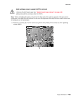
7100-XXX
High voltage power supply (HVPS) removal
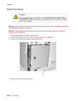
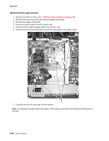
1.Remove the RIP board cage. See
“System board cage removal” on page 4-38
.
2.Disconnect all the connectors from the HVPS.
Note:
When reinstalling flat cables, ensure that the blue side of the cable is opposite of the pins on the
connectors. Flat cable pins are exposed on only one side (opposite blue side) and must make contact with
the metal pins on the connectors.
3.
Remove 11 screws (A) (4 corner screws are gold in color (metal); inner screws are silver (plastic));
remove HVPS.
A