LiftMaster 3265 3265M Manual
LiftMaster 3265 Manual
 |
View all LiftMaster 3265 manuals
Add to My Manuals
Save this manual to your list of manuals |
LiftMaster 3265 manual content summary:
- LiftMaster 3265 | 3265M Manual - Page 1
Chamberlain Group, Inc. 845 Larch Avenue Elmhurst, Illinois 60126-1196 www.liftmaster.com ® GARAGE DOOR OPENER Models 3265M 1/2 HP 3265M-267 1/2 HP For Residential Use Only Owner's Manual ■ Please read this manual and the enclosed safety materials carefully! ■ Fasten the manual near the garage door - LiftMaster 3265 | 3265M Manual - Page 2
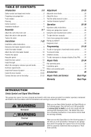
35 Repair Parts and Service Back Page Warranty Back Page INTRODUCTION Safety Symbol and Signal Word Review This garage door opener has been designed and tested to offer safe service provided it is installed, operated, maintained and tested in strict accordance with the instructions and warnings - LiftMaster 3265 | 3265M Manual - Page 3
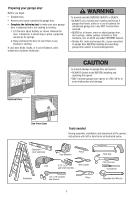
damage to garage door and opener: • ALWAYS disable locks BEFORE installing and operating the opener. • ONLY operate garage door opener at 120V, 60 Hz to avoid malfunction and damage. One-Piece Door Tools needed During assembly, installation and adjustment of the opener, instructions will call - LiftMaster 3265 | 3265M Manual - Page 4
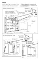
you proceed with the installation of your opener. SECTIONAL DOOR INSTALLATION Horizontal and vertical reinforcement is needed for lightweight garage doors (fiberglass, steel, aluminum, door with glass panels, etc.). See page 19 for details. Header Wall FINISHED CEILING Support bracket & fastening - LiftMaster 3265 | 3265M Manual - Page 5
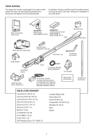
the packing material. Parts may be stuck in the foam. Hardware for installation is also listed below. LOCK LIGHT Multi-Function Door Control Panel SECURITY✚® Keyless Entry Model 3265M-267 Only SECURITY✚® 3-Button Remote Control Model 3265M (1) Model 3265M-267 (2) Chain Sprocket Cover Styrofoam - LiftMaster 3265 | 3265M Manual - Page 6
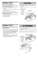
Unit To avoid installation difficulties, do not run the garage door opener until instructed to do so. • Remove the two washered bolts mounted in top of motor unit. • Position rail at a 45˚ angle to opener so one hole in rail and motor unit line up. • Thread one of the washered bolts part way in. Use - LiftMaster 3265 | 3265M Manual - Page 7
connect garage door opener to power source until instructed to do so. 8. NEVER wear watches, rings or loose clothing while installing or servicing opener. They could be caught in garage door or opener mechanisms. 9. Install wall-mounted garage door control: • within sight of the garage door. • out - LiftMaster 3265 | 3265M Manual - Page 8
CEILING MOUNT FOR HEADER BRACKET Structural Supports Level (optional) Installation procedures vary according to garage door types. Follow the instructions which apply to your door. 1. Close the door and mark the inside vertical centerline of the garage door. 2. Extend the line onto the header - LiftMaster 3265 | 3265M Manual - Page 9
garage door, or to the ceiling. Follow the instructions which will work best for your particular requirements. Do not install the header bracket over drywall. If installing Structural Support HARDWARE SHOWN ACTUAL SIZE Lag Screw 5/16"-9x1-5/8" Horizontal Line Highest Point of Garage Door Travel - LiftMaster 3265 | 3265M Manual - Page 10
Ring Fastener Clevis Pin 5/16"x2-3/4" Rail Chain Pulley Bracket Rail Garage Door Clevis Pin 5/16"x2-3/4" Temporary Support INSTALLATION STEP 4 Position the Opener Follow instructions which apply to your door type as illustrated. SECTIONAL DOOR OR ONE-PIECE DOOR WITH TRACK A 2x4 laid flat is - LiftMaster 3265 | 3265M Manual - Page 11
lag screws. To avoid possible SERIOUS INJURY from a falling garage door opener, fasten it securely to structural supports of the garage. Concrete anchors MUST be used if installing ANY brackets into masonry. Figure 1 Structural Supports Measure Distance Bolt 5/16"-18x7/8" Lock Washer 5/16" Nut - LiftMaster 3265 | 3265M Manual - Page 12
from a closing garage door: • Install door control within sight of garage door, out of reach of children at a minimum height of 5 feet (1.5 m), and away from ALL moving parts of door. • NEVER permit children to operate or play with door control push buttons or remote control transmitters. • Activate - LiftMaster 3265 | 3265M Manual - Page 13
due to vibration, replace with a Garage Door Opener bulb. • Use A19, standard neck garage door opener bulbs for replacement. NOTE: Use only standard light bulbs. The use of short neck or speciality light bulbs may overheat the endpanel or light socket. To prevent possible OVERHEATING of the - LiftMaster 3265 | 3265M Manual - Page 14
or DEATH from electrocution or fire: • Be sure power is NOT connected to the opener, and disconnect power to circuit BEFORE removing cover to establish permanent wiring connection. • Garage door installation and wiring MUST be in compliance with ALL local electrical and building codes. • NEVER use - LiftMaster 3265 | 3265M Manual - Page 15
) are available if needed. If installing in masonry construction, add a piece of wood at each location to avoid drilling extra holes in masonry if repositioning is necessary. The invisible light beam path must be unobstructed. No part of the garage door (or door tracks, springs, hinges, rollers or - LiftMaster 3265 | 3265M Manual - Page 16
Be sure power to the opener is disconnected. Install and align the brackets so the sensors will face each other across the garage door, with the beam no higher than 6" (15 cm) above the floor. They may be installed in one of three ways, as follows. Garage door track installation (preferred) (Figure - LiftMaster 3265 | 3265M Manual - Page 17
the bell wire from both sensors to the garage door opener. Attach the wire to the wall and ceiling with the staples (Figure 6). Option B - Pre-Wired Installation: If your garage already has wires installed for the safety reversing sensors, follow the instructions below: • Cut the end of the safety - LiftMaster 3265 | 3265M Manual - Page 18
the sender's beam. When the green indicator light glows steadily, tighten the wing nut. TROUBLESHOOTING THE SAFETY REVERSING SENSORS 1. If the sending eye indicator light does not glow steadily after installation, check for: • Electric power to the opener. • A short in the white or white/black - LiftMaster 3265 | 3265M Manual - Page 19
brace. For the vertical brace, 2 pieces of angle iron are used to create a U-shaped support. The best solution is to check with your garage door manufacturer for an opener installation door reinforcement kit. NOTE: Many door reinforcement kits provide for direct attachment of the clevis pin and - LiftMaster 3265 | 3265M Manual - Page 20
for your installation. (Refer to the dotted line optional placement drawing.) HARDWARE SHOWN ACTUAL SIZE Self-Threading Screw 1/4"-14x5/8" Header Wall - Finished Ceiling - Header Bracket 2x4 Support Door Bracket Door Bracket Optional Placement of Door Bracket Vertical Centerline of Garage Door - LiftMaster 3265 | 3265M Manual - Page 21
INSTALLATION STEP 12 Connect Door Arm to Trolley Follow instructions which apply to your door type as illustrated below and on the following page. SECTIONAL DOORS ONLY Make sure garage door is fully closed. Pull the emergency release handle to disconnect the outer trolley from the inner trolley. - LiftMaster 3265 | 3265M Manual - Page 22
cause unnecessary bucking and/or jerking operation as the door is being opened or closed from the fully open position. Door Arm Door Arm Connector Hole Closed Door Emergency Release Handle Inner Trolley Correct Angle Door Arm Outer Trolley Open Door 22 Door with Backward Slant (Incorrect) - LiftMaster 3265 | 3265M Manual - Page 23
travel cycle: If the opener lights are flashing, the Safety Reversing Sensors are either not installed, misaligned, or obstructed. See Troubleshooting, page 18. Test the door for binding: Pull the emergency release handle. Manually open and close the door. If the door is binding or unbalanced, call - LiftMaster 3265 | 3265M Manual - Page 24
, run the opener through a complete travel cycle. Without a properly installed safety reversal system, persons (particularly small children) could be SERIOUSLY INJURED or KILLED by a closing garage door. • Too much force on garage door will interfere with proper operation of safety reversal - LiftMaster 3265 | 3265M Manual - Page 25
System® • Press the remote control push button to open the door. • Place the opener carton in the path of the door. • Press the remote control push button to close the door. The door will not move more than an inch (2.5 cm), and the opener lights will flash. The garage door opener will not close from - LiftMaster 3265 | 3265M Manual - Page 26
THESE obstructions. 8. NEVER use handle to pull garage door open or INSTRUCTIONS. closed. If rope knot becomes untied, you could fall. Using Your Garage Door Opener 6. If obstructed while opening, the door will stop. Your Security✚® opener and hand-held remote control have been factory-set to - LiftMaster 3265 | 3265M Manual - Page 27
the Lock button on the door control. 3. Press and hold the door control push bar. 4. After the opener lights flash, release all buttons. To Open the Door Manually Lock feature Designed to prevent operation of the door from hand-held remote controls. However, the door will open and close from the - LiftMaster 3265 | 3265M Manual - Page 28
the door tracks. Two Times a Year • Check chain tension. Disconnect trolley first. Adjust if necessary (see page 7). Every Three to Four Years • Use a rag to wipe away the existing grease from the garage door opener rail. Reapply a small layer of white lithium grease to the rail. THE REMOTE CONTROL - LiftMaster 3265 | 3265M Manual - Page 29
Having a Problem? 1. My door will not close and the light bulbs blink on my motor unit: The safety reversing sensor must be connected and aligned correctly before the garage door opener will move in the down direction. • Verify the safety sensors are properly installed, aligned and free of any - LiftMaster 3265 | 3265M Manual - Page 30
FLASHES Door control or wire shorted. 4 FLASHES Safety reversing sensors slightly misaligned (dim or flashing LED). 5 FLASHES Motor overheated or possible RPM sensor failure. Unplug to reset. 6 FLASHES Motor Circuit Failure. Replace Receiver Logic Board. Symptom: One or both of the indicator lights - LiftMaster 3265 | 3265M Manual - Page 31
4. Release buttons when the motor unit lights blink. It has learned the code. If light bulbs are not installed, two clicks will be heard. *3-Button Remotes If provided with your garage door opener, the large button is factory programmed to operate it. Additional buttons on any Security✚® 3-Button - LiftMaster 3265 | 3265M Manual - Page 32
PIN NOTE: Your new Keyless Entry must be programmed to operate your garage door opener. USING THE "LEARN" BUTTON USING THE MULTI-FUNCTION DOOR CONTROL 1. Press and release the "learn" button on motor unit. The learn indicator light will glow steadily for 30 seconds. 2. Within 30 seconds, enter - LiftMaster 3265 | 3265M Manual - Page 33
8' (2.4 m) 1710LM One-piece rail - 10' (3 m) 5 41D3484 Full chain assembly 6 83A11-2 Rail grease Installation Parts 13 6 5 8 12 11 4 2 10 9 KEY PART NO. NO. DESCRIPTION 1 41A5273-1 Multi-function door control panel 2 373LM 3 Button remote control 3 10A20 3V2032 Lithium battery 4 29B137 - LiftMaster 3265 | 3265M Manual - Page 34
Cover 13 41A2818 Limit switch drive & retainer 14 41D3452 Limit switch assembly 15 41A2822-1 Interrupter cup assembly 16 41C4398A RPM sensor assembly 17 41AC050-2M Receiver logic board assembly Complete with: Logic board, end panel w/all labels, light socket 18 41C5498 41C5497 Low voltage - LiftMaster 3265 | 3265M Manual - Page 35
LiftMaster Security✚® remote. 41A5281 78LM LOCK LIGHT Extension Brackets: (Optional) For safety sensor installation onto the wall or floor. 373W 373LM Multi-Function Door Control Panel: Provides a Lock Feature which prevents operation of garage door opener from portable remotes and a Light - LiftMaster 3265 | 3265M Manual - Page 36
: 1-800-528-9131 www.liftmaster.com For professional installation, parts and service, contact your local LIFTMASTER/CHAMBERLAIN dealer. Look for him in the Yellow Pages, or call our Service number for a list of dealers in your area. HOW TO ORDER REPAIR PARTS Selling prices will be furnished on
-
 1
1 -
 2
2 -
 3
3 -
 4
4 -
 5
5 -
 6
6 -
 7
7 -
8
-
9
-
10
-
11
-
12
-
13
-
14
-
15
-
16
-
17
-
18
-
19
-
20
-
21
-
22
-
23
-
24
-
25
-
26
-
27
-
28
-
29
-
30
-
31
-
32
-
33
-
34
-
35
-
36
 |
 |
The Chamberlain Group, Inc.
845 Larch Avenue
Elmhurst, Illinois 60126-1196
www.liftmaster.com
GARAGE DOOR OPENER
Models
3265M 1/2 HP
3265M-267 1/2 HP
For Residential Use Only
Owner’s Manual
■
Please read this manual and the enclosed safety materials carefully!
■
Fasten the manual near the garage door after installation.
■
The door WILL NOT CLOSE unless the Protector System
®
is connected and properly aligned.
■
Periodic checks of the opener are required to ensure safe operation.
■
The model number label is located on the front panel of your opener.
®