LiftMaster 3950 3950 Manual
LiftMaster 3950 Manual
 |
View all LiftMaster 3950 manuals
Add to My Manuals
Save this manual to your list of manuals |
LiftMaster 3950 manual content summary:
- LiftMaster 3950 | 3950 Manual - Page 1
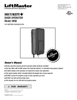
® DOOR OPERATOR Model 3950 For Light Duty Commercial Use The Chamberlain Group, Inc. 845 Larch Avenue Elmhurst, Illinois 60126-1196 www.liftmaster.com Com patible with Owner's Manual ■ Please read this manual and the enclosed safety materials carefully! ■ The door WILL NOT CLOSE unless The - LiftMaster 3950 | 3950 Manual - Page 2
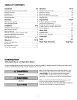
9 Install The Protector System 10-12 Adjustment 13-15 Program the travel limits 13 Set the force 14 Test The Protector System 15 To open door manually 15 Operation 16-18 Operation safety instructions 16 Using your operator 16 Care of your operator 16 Having a problem? (Troubleshooting - LiftMaster 3950 | 3950 Manual - Page 3
for more information. For live shaft type doors the drive shaft needs to extend 1-1/2" beyond the door mount bracket. • If the operator is mounted below 8 feet (2.5 m), a chain guard must be installed to protect against possible injury. See accessories page. To prevent possible SERIOUS INJURY or - LiftMaster 3950 | 3950 Manual - Page 4
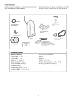
parts illustrated below. Note that accessories will depend on the model purchased. If anything is missing, carefully check the packing material. 2-Conductor Bell Wire White & White/Red Mounting Bracket (4) Operator Door Sprockets Safety Labels and Literature Hardware Inventory Installation - LiftMaster 3950 | 3950 Manual - Page 5
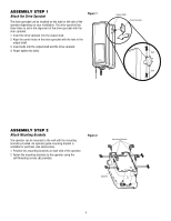
Attach Mounting Brackets The operator can be mounted to the wall with the mounting brackets provided. An optional guide mounting bracket is available for purchase (see accessories). 1. Position two mounting brackets on each side of the operator. 2. Fasten the mounting brackets to the operator using - LiftMaster 3950 | 3950 Manual - Page 6
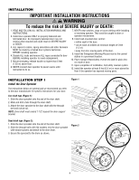
(1.83 m) above floor. 6. NEVER connect door operator to power source until instructed to do so. 7. NEVER wear watches, rings or loose clothing while installing or servicing operator. They could be caught in door or operator mechanisms. 8. Install wall-mounted door control: • within sight of the - LiftMaster 3950 | 3950 Manual - Page 7
INSTALLATION STEP 2 Mount the Operator The operator can be mounted to the wall with the mounting brackets provided. An optional guide mounting bracket is available for purchase (see accessories). Fasten the operator to the mounting surface using appropriate method and hardware (not provided). - LiftMaster 3950 | 3950 Manual - Page 8
or DEATH from a closing door: • Install door control within sight of door, out of reach of children at a minimum height of 5 feet (1.5 m) and away from ALL moving parts of door. • NEVER permit children to operate or play with door control push buttons or remote controls. • Activate door ONLY when it - LiftMaster 3950 | 3950 Manual - Page 9
to establish permanent wiring connection. • Door installation and wiring MUST be in compliance with ALL local electrical and building codes. • NEVER use an extension cord, 2-wire adapter or change plug in ANY way to make it fit outlet. Be sure the operator is grounded. PERMANENT WIRING CONNECTION - LiftMaster 3950 | 3950 Manual - Page 10
. Extension brackets (see accessories) are available if needed. If installing in masonry construction, add a piece of wood at each location to avoid drilling extra holes in masonry if repositioning is necessary. The invisible light beam path must be unobstructed. No part of the door (door tracks - LiftMaster 3950 | 3950 Manual - Page 11
(Not provided). • If using extension brackets or wood blocks, adjust right and left assemblies to the same distance out from the mounting surface. Make sure all door hardware obstructions are cleared. Floor installation (Figure 3): • Use wood blocks or extension brackets (see accessories) to elevate - LiftMaster 3950 | 3950 Manual - Page 12
, with lenses pointing toward each other across the door. Be sure the lens is not obstructed by a bracket extension (Figure 4). • Finger tighten the wing nuts. • Run the wires from both safety reversing sensors to the operator. Use insulated staples to secure wire to wall and ceiling. • Strip - LiftMaster 3950 | 3950 Manual - Page 13
regulate the points at which the door will stop when moving up or down. Adjust the position of the door by using the black and purple buttons. Black moves the door UP (open) and purple moves the door DOWN (close). NOTE: The safety reversing sensors MUST be installed to program the limits. Figure - LiftMaster 3950 | 3950 Manual - Page 14
button twice to enter into the Force Adjustment Mode. The LED will flash quickly. 2. Push the remote control or door control. The door will close (DOWN). 3. Push the remote control or door control again. The door will open (UP). 4. Push the remote control or door control a third time to close the - LiftMaster 3950 | 3950 Manual - Page 15
not operate the door. Call for a trained door systems technician. Without a properly installed safety reversing sensor, persons (particularly small children) could be SERIOUSLY INJURED or KILLED by a closing door. Safety Reversing Sensor Safety Reversing Sensor ADJUSTMENT STEP 4 To Open the Door - LiftMaster 3950 | 3950 Manual - Page 16
garage door opener BEFORE making ANY repairs or removing covers. 13. SAVE THESE INSTRUCTIONS. Using Your Operator Press and hold the push button on the single button control station until the door starts to move. When the operator is activated (with the safety reversing sensor correctly installed - LiftMaster 3950 | 3950 Manual - Page 17
control station: • Are the wiring connections correct? Review Installation Step 4. 3. The door operates from the single button control station, but not from the remote control: • Program the operator to match the remote control code. (Refer to instructions on the motor unit panel.) Repeat with all - LiftMaster 3950 | 3950 Manual - Page 18
installed jumper loose or missing. Installed Safety Reversing Sensor Your door operator • Reattach sending eye to motor unit using shortened wires. If sending eye indicator brackets. Symptom: Door travels 2-3 inches and stops. • Reprogram limits and forces. See Adjustments section. • If the operator - LiftMaster 3950 | 3950 Manual - Page 19
copyright in the door operator does not authorize the purchaser or supplier of the non-rolling code transmitter to circumvent that technical measure. To Add or Program a Hand-held Remote Control (Not Provided) Below are instructions for programming your operator to operate with optional Security - LiftMaster 3950 | 3950 Manual - Page 20
optional remote light is installed, the light will blink. To set a temporary PIN You may authorize access by visitors or service people with a temporary 4-digit PIN. After a programmed number of hours or number of accesses, this temporary PIN expires and will no longer open the door. It can be used - LiftMaster 3950 | 3950 Manual - Page 21
Parts 3 4 1 2 NOTICE 5 KEY PART NO. NO. DESCRIPTION 1 APBS 1 Single button control station 2 41A6298-5 Emergency release rope, handle assembly and installation hardware bag (includes hardware listed on page 4) 3 41B4494-1 2-conductor bell wire white & white/red 4 41C0902 Mounting bracket - LiftMaster 3950 | 3950 Manual - Page 22
Security✚® Remote Control : Includes visor clip. EverCharge® Standby Power System: Provides backup power to the model 3900 door operator. Power Door Lock: Enables the end user to prevent the door from being manually opened once closed. Guide Mounting Bracket Kit: The bracket can be mounted in - LiftMaster 3950 | 3950 Manual - Page 23
NOTES 23 - LiftMaster 3950 | 3950 Manual - Page 24
: 1-800-528-2806 www.liftmaster.com For professional installation, parts and service, contact your local LIFTMASTER/CHAMBERLAIN dealer. Look for him in the Yellow Pages, or call our Service number for a list of dealers in your area. HOW TO ORDER REPAIR PARTS Selling prices will be furnished on
-
 1
1 -
 2
2 -
 3
3 -
 4
4 -
 5
5 -
 6
6 -
 7
7 -
8
-
9
-
10
-
11
-
12
-
13
-
14
-
15
-
16
-
17
-
18
-
19
-
20
-
21
-
22
-
23
-
24
 |
 |

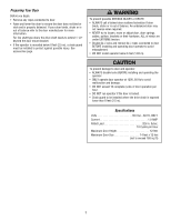
Owner’s Manual
■
Please read this manual and the enclosed safety materials carefully!
■
The door WILL NOT CLOSE unless The Protector System
®
is connected and properly aligned.
■
Periodic checks of the operator are required to ensure safe operation.
■
The model number label is located behind the hinged door of your operator.
■
DO NOT exceed 10 complete cycles of door operation per hour.
■
DO NOT use with sectional type doors.
■
This manual is to be left with the property owner.
DOOR OPERATOR
Model 3950
For Light Duty Commercial Use
The Chamberlain Group, Inc.
845 Larch Avenue
Elmhurst, Illinois 60126-1196
www.liftmaster.com
®
C
o
m
p
a
t
i
b
l
e
w
i
t
h
Serial #
(Located on electrical box cover)
Installation Date
2
YEAR
WARRANTY