LiftMaster APT APT LOGIC VERSION 2 Manual
LiftMaster APT Manual
 |
View all LiftMaster APT manuals
Add to My Manuals
Save this manual to your list of manuals |
LiftMaster APT manual content summary:
- LiftMaster APT | APT LOGIC VERSION 2 Manual - Page 1
service. 41B6 LISTED DOOR OPERATOR This addendum is to be used in conjunction with T manual 01-17278. Refer to manual 01-17278 for all mounting and wiring instructions. APT specifications and component identification are included with this addendum. For specifications, service, or replacement part - LiftMaster APT | APT LOGIC VERSION 2 Manual - Page 2
MODEL APT - REPLACEMENT PARTS LIST INDIVIDUAL COMPONENTS ITEM PART # DESCRIPTION QTY 1 10-10030 Frame Spacer Bracket 1 2 K20-1050B2RL Motor Kit (BAPT5011L2 & BAPT5021L2) 1 K20-3050B4RL Motor Kit (BAPT5023L2 & BAPT5043L2) 1 3 K-BAPT5011 Electrical Box Kit (Model BAPT5011L2) 1 K-BAPT5021 - LiftMaster APT | APT LOGIC VERSION 2 Manual - Page 3
MODEL APT - ILLUSTRATED PARTS H5 H3 H6 H7 4 H4 1 H2 H1 O2 O4 S2 S5 O2 O5 O9 O3 O6 S3 S2 O11 O10 O1 O9 S8 C13 S1 S7 C16 C3 C2 C15 C14 O12 2 O7 S4 C1 C6 C8 C7 C11 C5 C12 C3 C4 B14 B12 B11 B8 3 B10 B9 B7 B14 B5 B15 B11 B11 B13 B3 B4 B2 B6 B14 B15 B1 BRAKE ASSEMBLY 3 - LiftMaster APT | APT LOGIC VERSION 2 Manual - Page 4
OPEN & STOP, constant pressure to CLOSE, open override plus wiring for sensing device to reverse. See Model T Manual pages 16, 17 and 18 for optional wiring types and operating Bearing. SAFETY DISCONNECT Quick disconnect door arm for emergency manual door operation. REVERSING EDGE: ....(Optional)
-
 1
1 -
 2
2 -
 3
3 -
 4
4
 |
 |
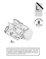
ADDENDUM
MODEL APT
LOGIC CONTROL (VER. 2.0)
INDUSTRIAL DUTY DOOR OPERATOR
This addendum is to be used in conjunction with T manual 01-17278.
Refer
to manual 01-17278 for all mounting and wiring instructions.
APT specifi-
cations and component identification are included with this addendum.
For
specifications, service, or replacement part requirements, use this adden-
dum in lieu of those include with the manual.
LISTED
DOOR
OPERATOR
41B6
LOGIC CONTROL
L
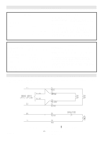
C2 Wiring
FACTORY SET
See pages 13 & 14
for other wiring
configurations
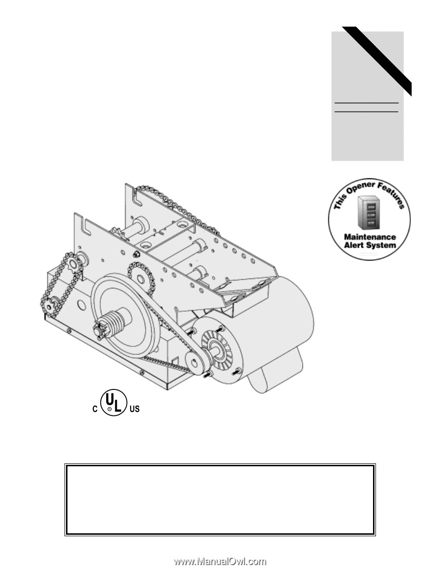
The Maintenance Alert System
allows the installer to set an internal
Maintenance Cycle Counter.
An LED
on the 3-button station will signal when
the set number of cycles is reached or
when the opener requires immediate
service.
TM
PATENT PENDING