LiftMaster APT APT LOGIC VERSION 2 Manual - Page 4
Specifications, Motor Wiring Diagram - 115/230 Volt / Single Phase - manual
 |
View all LiftMaster APT manuals
Add to My Manuals
Save this manual to your list of manuals |
Page 4 highlights
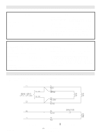
SPECIFICATIONS MOTOR TYPE Continuous duty HORSEPOWER 1/2 Hp SPEED 1725 RPM VOLTAGE 115/230 Volts - Single phase 230/460 Volts - Three phase CURRENT See motor nameplate ELECTRICAL TRANSFORMER 24VAC CONTROL STATION: ......NEMA 1 three button station. OPEN/CLOSE/STOP W/ LED WIRING TYPE C2 (Factory Shipped) Momentary contact to OPEN & STOP, constant pressure to CLOSE, open override plus wiring for sensing device to reverse. See Model T Manual pages 16, 17 and 18 for optional wiring types and operating modes. LIMIT ADJUST Linear driven, fully adjustable screw type cams. Adjustable to 24 feet. MECHANICAL DRIVE REDUCTION Primary: Heavy duty (5L) V-Belt. Secondary: #41 chain/sprocket. Output: #48 chain OUTPUT SHAFT SPEED:.....96 R.P.M. DOOR SPEED 7 - 8" per sec. depending on door BRAKE:(Optional Solenoid actuated disc BEARINGS Output Shaft: Shielded Ball Bearing. Clutch & Intermediate Shaft: Shielded Ball Bearing. SAFETY DISCONNECT Quick disconnect door arm for emergency manual door operation. REVERSING EDGE: ....(Optional) Electric or pneumatic sensing device attached to the bottom edge of door. A REVERSING DEVICE IS STRONGLY RECOMMENDED FOR ALL COMMERCIAL OPERATOR INSTALLATIONS. REQUIRED WHEN THE 3 BUTTON CONTROL STATION IS OUT OF SIGHT OF DOOR OR ANY OTHER CONTROL (AUTOMATIC OR MANUAL) IS USED. MOTOR WIRING DIAGRAM - 115/230 VOLT / SINGLE PHASE See below for internal wiring of motor in lieu of the motor diagrams shown in Model T owner's manual. See Model T owner's manual for all power and control connections. 01-10384H NOTE: Refer to T logic II Manual for O3 (3-Phase) wiring. c 2002, The Chamberlain Group, Inc. All rights Reserved
-
 1
1 -
 2
2 -
 3
3 -
 4
4
 |
 |
