LiftMaster BG790 BG790 Manual - Page 10
Caution
 |
View all LiftMaster BG790 manuals
Add to My Manuals
Save this manual to your list of manuals |
Page 10 highlights
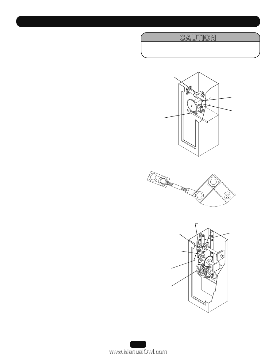
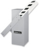
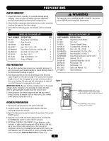
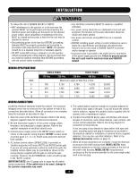
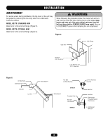
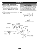
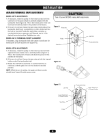
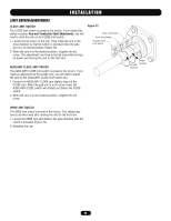
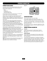
INSTALLATION ARM AND TURNBUCKLE SHAFT ADJUSTMENTS MODEL BG770 ADJUSTMENTS 1. If necessary, rotate the pulley on the motor by hand until the crank arm on the gear reducer is perfectly aligned with the turnbuckle shaft (Figure 9). This is the lowest point of the arm travel and should be preset in this position at the factory. 2. If the arm is not level, loosen the jam nuts at both ends of the turnbuckle shaft Insert a screwdriver or other similar tool into the hole in the shaft. Rotate the shaft either clockwise or counterclockwise as necessary until the gate arm is in the desired horizontal position. Retighten jam nuts. MODEL BG770 TURNBUCKLE SHAFT ALIGNMENT If necessary, align turnbuckle shaft with center of crank arm for lowest point of travel of pivot arm (Figure 10). MODEL BG790 ADJUSTMENTS 1. If necessary, rotate the pulley on the motor by hand until the upper and lower cranks are in a vertical position (Figure 11). This is the lowest point of travel and should be preset in this position at the factory. 2. If the arm is not level, loosen the jam nuts on both the top and bottom end of the turnbuckle shaft. 3. Rotate the shaft either clockwise or counterclockwise as necessary until the gate arm is in the desired horizontal position. NOTE: While the arm is raising, the upper and lower cranks should travel toward the side access cover. CAUTION Turn off power BEFORE making ANY adjustments. Figure 9 Pivot Arm Pulley Crank Arm Jam Nut Turnbuckle Shaft Figure 10 Figure 11 Jam Nut Lower Crank Arm in Closed Position See Note Pulley Turnbuckle Shaft Upper Crank Arm in Closed Position 10
-
 1
1 -
2
-
3
-
4
-
 5
5 -
 6
6 -
 7
7 -
 8
8 -
 9
9 -
 10
10 -
 11
11 -
 12
12 -
 13
13 -
 14
14 -
 15
15 -
16
-
17
-
18
-
19
-
20
-
21
-
22
-
23
-
24
 |
 |