LiftMaster CSW24UL Installation Manual - Page 43
SYMPTOM, POSSIBLE CAUSES, SOLUTIONS, Edge Sensor does
 |
View all LiftMaster CSW24UL manuals
Add to My Manuals
Save this manual to your list of manuals |
Page 43 highlights
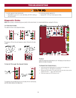
TROUBLESHOOTING SYMPTOM Gate closes, but will not open. Exit loop activation does not cause gate to open. Interrupt loop does not cause gate to stop and reverse. Shadow loop does not keep gate at open limit. Obstruction in gate's path does not cause gate to stop and reverse. Photoelectric sensor does not stop or reverse gate. Edge Sensor does not stop or reverse gate. Alarm sounds for 5 minutes or alarm sounds with a command. Alarm beeps three times with a command. On dual-gate system, incorrect gate opens first or closes first. Alarm beeps when running. Expansion board function not controlling gate. Maglock not working correctly. POSSIBLE CAUSES a. Vehicle loop detector active b. Low battery with LOW BATT option set to CLOSE a. Exit vehicle detector setup incorrectly b. Defective Exit loop detector c. Low battery with LOW BATT option set to CLOSE a. Vehicle detector setup incorrectly b. Defective vehicle loop detector c. Anti-tail set to ON a. Vehicle detector setup incorrectly b. Defective vehicle loop detector a. Force adjustment needed a. Incorrect photoelectric sensor wiring b. Defective photoelectric sensor a. Incorrect edge sensor wiring b. Defective edge sensor a. Double entrapment occurred (two obstructions within a single activation) a. Low battery a. Incorrect Bipart switch setting a. Expansion board setting b. Constant pressure to open or close is given a. Defective main board to expansionboard wiring b. Incorrect input wiring to expansion board c. Defective expansion board or defective main board a. Maglock wired incorrectly SOLUTIONS a. Check all vehicle detector inputs for an active detector b. Check if AC power is available. If no AC power, then running on batteries and battery voltage must be 23.0 Vdc or higher. Charge batteries by AC or solar power or replace batteries. a. Review Exit loop detector settings. Adjust settings as needed. b. Replace defective Exit loop detector. c. Check if AC power is available. If no AC power, then running on batteries and battery voltage must be 23.0 Vdc or higher. Charge batteries by AC or solar power or replace batteries. a. Review Interrupt loop detector settings. Adjust settings as needed. b. Replace defective Interrupt loop detector. c. Set anti-tail to OFF. a. Review Shadow loop detector settings. Adjust settings as needed. b. Replace defective Shadow loop detector. a. Refer to the Adjustment section to conduct the obstruction test and perform the proper force adjustment that is needed. a. Check photoelectric sensor wiring. Retest that obstructing photoelectric sensor causes moving gate to stop, and may reverse direction. b. Replace defective photoelectric sensor. Retest that obstructing photoelectric sensor causes moving gate to stop, and may reverse direction. a. Check edge sensor wiring. Retest that activating edge sensor causes moving gate to stop and reverse direction. b. Replace defective edge sensor. Retest that activating edge sensor causes moving gate to stop and reverse direction. a. Check for cause of entrapment (obstruction) detection and correct. Press the reset button to shut off alarm and reset the operator. a. Check if AC power is available. If no AC power, then running on batteries and battery voltage must be 23.0 Vdc or higher. Charge batteries by AC or solar power or replace batteries a. Change setting of both operator's Bipart switch settings. One operator should have Bipart switch ON (operator that opens second) and the other operator should have Bipart switch OFF (operator that opens first). a. Pre-warning is set to "ON" b. Constant pressure to open or closed is given a. Check main board to expansion board wiring. If required, replace wire cable. b. Check wiring to all inputs on expansion board. c. Replace defective expansion board or defective main board a. Check that Maglock is wired to N.C. and COM terminals. Check that Maglock has power (do not power maglock from control board accessory power terminals). If shorting lock's NO and COM wires does not activate Maglock, then replace Maglock or Maglock wiring (refer to Wiring Diagrams). 43
-
 1
1 -
2
-
3
-
4
-
5
-
6
-
7
-
8
-
9
-
10
-
11
-
12
-
13
-
14
-
15
-
16
-
17
-
18
-
19
-
20
-
21
-
22
-
23
-
24
-
25
-
26
-
27
-
28
-
29
-
30
-
31
-
32
-
33
-
34
-
35
-
36
-
37
-
 38
38 -
 39
39 -
 40
40 -
 41
41 -
 42
42 -
 43
43 -
 44
44 -
 45
45 -
 46
46 -
 47
47 -
 48
48 -
49
-
50
-
51
-
52
-
53
-
54
-
55
-
56
 |
 |
