LiftMaster H J LOW PROFILE ELEC.BOX Manual
LiftMaster H Manual
 |
View all LiftMaster H manuals
Add to My Manuals
Save this manual to your list of manuals |
LiftMaster H manual content summary:
- LiftMaster H | J LOW PROFILE ELEC.BOX Manual - Page 1
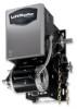
OWNER'S MANUAL MODELS: J 3 H 3 HJ INDUSTRIAL DUTY DOOR OPERATOR FACTORY SET C2 Wiring See page 8 for other wiring configurations 2 YEAR WARRANTY Serial # (located on electrical box cover) Installation Date Wiring Type NOT FOR RESIDENTIAL USE 41B6 LISTED DOOR OPERATOR - LiftMaster H | J LOW PROFILE ELEC.BOX Manual - Page 2
OTHER CONTROL (AUTOMATIC OR MANUAL) IS USED. WEIGHTS AND DIMENSIONS HANGING WEIGHT: .........80-110 LBS. 14.50" 7.25" 20.91" 8.00" 7.50" 13.00" 4.63 4.41" MOUNTING DIMENSIONS A - Wall Mounting B - Bracket Mounting (rolling door) 7.50" 6.63" A B 5.50" B 1.50" A B 13.75" B 16.50" Hand Chain - LiftMaster H | J LOW PROFILE ELEC.BOX Manual - Page 3
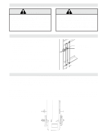
NOTES CAUTION TO AVOID DAMAGE TO DOOR AND OPERATOR, MAKE ALL DOOR LOCKS INOPERATIVE. SECURE LOCK(S) IN "OPEN" POSITION. IF THE DOOR LOCK NEEDS TO REMAIN FUNCTIONAL, INSTALL AN INTERLOCK SWITCH. DO NOT CONNECT ELECTRIC POWER UNTIL INSTRUCTED TO DO SO. WARNING KEEP DOOR BALANCED. STICKING OR BINDING - LiftMaster H | J LOW PROFILE ELEC.BOX Manual - Page 4
Optimum Distance 12 - 15" Optimum Distance 12 - 15" Typical Right Hand Wall Mounted Operator FIGURE 3 IMPORTANT: The shelf or bracket must provide adequate support, prevent play between operator and door shaft, and permit operator to be fastened securely and with the drive shaft parallel to the - LiftMaster H | J LOW PROFILE ELEC.BOX Manual - Page 5
with Hoist for Models H and HJ Keyhole Bracket Model HJ This operator includes both, a floor level disconnect chain to disconnect the door from the door operator and and a disconnect chain with manual hoist to electrically disable the electrical controls. 1. Refer to model H instructions for hoist - LiftMaster H | J LOW PROFILE ELEC.BOX Manual - Page 6
open (N.O.) output are compatible with your operator. This includes pneumatic and electric edges. If your door does operator. If not pre-installed by the door manufacturer, mount the sensing edge on the door according to the instructions provided with the edge. The sensing edge may be electrically - LiftMaster H | J LOW PROFILE ELEC.BOX Manual - Page 7
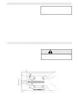
ON UNTIL YOU HAVE FINISHED MAKING ALL POWER AND CONTROL WIRING CONNECTIONS AND HAVE COMPLETED THE LIMIT SWITCH ADJUSTMENT PROCEDURE. TO AVOID DAMAGE TO DOOR AND OPERATOR, MAKE ALL DOOR LOCKS INOPERATIVE. SECURE LOCK(S) IN "OPEN" POSITION. IF THE DOOR LOCK NEEDS TO REMAIN FUNCTIONAL, INSTALL AN - LiftMaster H | J LOW PROFILE ELEC.BOX Manual - Page 8
All operators are supplied with some type of control station. Generally a three button station (OPEN/CLOSE/STOP) is provided. A two-position key switch or control station (OPEN/CLOSE) may be added or substituted when requested at the time of order. Mount the control station near the door. WARNING - LiftMaster H | J LOW PROFILE ELEC.BOX Manual - Page 9
On all models with type B2 control wiring, a terminal bracket marked R1 R2 R3 is located on the outside of the electrical enclosure. All standard radio control receivers (single channel residential type) may be mounted to this bracket. The operator will then open a fully closed door, close a fully - LiftMaster H | J LOW PROFILE ELEC.BOX Manual - Page 10
Instructions, know how to electrically operate the door in a safe manner, and know how to use the manual disconnect operation of the door operating system. WARNING DO NOT PLACE HANDS OR TOOLS IN OR NEAR THE OPERATOR WHEN THE POWER IS ON OR WHEN TESTING CONTROL operator, call the parts and service - LiftMaster H | J LOW PROFILE ELEC.BOX Manual - Page 11
Belt Fasteners Manual Disconnect Check & tighten as required Check & Operate Check for wear & lubricate EVERY 3 MONTHS operation. s Do not lubricate clutch or V-belt. s Inspect and service whenever a malfunction is observed or suspected. s CAUTION: BEFORE SERVICING, ALWAYS DISCONNECT OPERATOR - LiftMaster H | J LOW PROFILE ELEC.BOX Manual - Page 12
BK) 230V MODELS 115V MODELS 115V BRAKE OPEN C LIMIT SWITCH NO R1 R2 CLOSE TIMER TO CLOSE (OPTIONAL) (PUR) (PUR) 2 (P) IR (R) C NO CLOSE R1 LIMIT SWITCH (PUR) (PUR) CL (PUR) (PUR) A2 A1 NC C 14 CL 13 NOTE: 1. Voltage same as line voltage. * - Shipped from Factory CLOSE CONTROL - LiftMaster H | J LOW PROFILE ELEC.BOX Manual - Page 13
-1 WARNING Always Disconnect Power Whenever Installing or Servicing the Door Operator. R1 ORANGE RADIO RECEIVER R2 YELLOW R3 RED RED AUX.TERMINAL BLOCK FOR RADIO C NO AUX.OPEN L/S NC YELLOW PURPLE ORANGE OPEN LIMIT SWITCHES OPEN L/S C NC ORANGE ORANGE CONTACTOR PURPLE RED YELLOW - LiftMaster H | J LOW PROFILE ELEC.BOX Manual - Page 14
YEL) HAND CHAIN YEL) OPEN (OR CONTROL WIRING OPTIONS *C2 WIRING - Constant Presssure to Close RED WIRE ON TERMINAL #2 (Shipped from Factory) B2 WIRING - Momentary Contact to Close MOVE RED WIRE FROM TERMINAL #2 TO TERMINAL #3 NOTE: 1. Voltage same as line voltage 2. Overload in motor for models - LiftMaster H | J LOW PROFILE ELEC.BOX Manual - Page 15
1742-3 WARNING Always Disconnect Power Whenever Installing or Servicing the Door Operator. RADIO RECEIVER R1 R2 R3 AUX.TERMINAL BLOCK FOR RADIO C NO AUX.OPEN L/S NC ORANGE YELLOW RED RED YELLOW PURPLE ORANGE OPEN LIMIT SWITCHES OPEN L/S NC C ORANGE ORANGE PURPLE RED YELLOW GREY PURPLE - LiftMaster H | J LOW PROFILE ELEC.BOX Manual - Page 16
ELECTRICAL BOX - ILLUSTRATED PARTS S4 S3 S9 S5 S1 S7 S6 S2 S8 L3 L1 6 7 1 10 L5 L8 L6 L2 3 11 2 4 16 L7 9 L2 L6 L4 8 5 - LiftMaster H | J LOW PROFILE ELEC.BOX Manual - Page 17
Disconnect Assy Kit, Left Hand Model J and Right Hand Model H to use right hand assembly, Left hand Model H to use left hand assy, Model HJ requires both assemblies Brake Kits 71-B120J 115 Volt Model J 71-B240J 230-460 Volt Model J 71-B575J 575 Volt Model J 71-B120H 115 Volt Model H 71-B240H 230 - LiftMaster H | J LOW PROFILE ELEC.BOX Manual - Page 18
ILLUSTRATED PARTS - Model J 5 6 7 1 8 9 C8 C20 C10 C9 C21 D1 D7 D4 D8 D11 D3 D10 D9 D2 D5 D6 C4 C6 C24 C7 C16 C23 C17 C14 C18 - LiftMaster H | J LOW PROFILE ELEC.BOX Manual - Page 19
-12558 RIGHT HAND DISCONNECT ASSY KIT ITEM D1 D2 D3 D4 D5 D6 D7 D8 D9 D10 D11 PART # 10-10707 10-10708 10-10875 10-10898 11-10878 19-8A-12 82-HN25-12 82-SH10-14 84-FN-10 84-FN-25 86-RP04-100 DESCRIPTION QTY Disconnect Support Bracket 1 Yoke 1 Disconnect - LiftMaster H | J LOW PROFILE ELEC.BOX Manual - Page 20
ILLUSTRATED PARTS - Model H 8 5 6 9 D1 D10 7 D7 1 D4 D9 D8 D11 D3 C12 D2 D5 D6 C15 C6 C2 C17 C5 C7 C19 C16 C18 C4 C25 C18 C19 - LiftMaster H | J LOW PROFILE ELEC.BOX Manual - Page 21
-12558 RIGHT HAND DISCONNECT ASSY KIT ITEM D1 D2 D3 D4 D5 D6 D7 D8 D9 D10 D11 PART # 10-10707 10-10708 10-10875 10-10898 11-10878 19-8A-12 82-HN25-12 82-SH10-14 84-FN-10 84-FN-25 86-RP04-100 DESCRIPTION QTY Disconnect Support Bracket 1 Yoke 1 Disconnect - LiftMaster H | J LOW PROFILE ELEC.BOX Manual - Page 22
ILLUSTRATED PARTS - MODEL HJ 22 8 6 1 L1 L7 L4 L10 L9 L8 L11 L3 C17 L2 L5 L6 C7 C2 C20 C6 C5 C22 C23 C30 C14 C19 O2 O11 - LiftMaster H | J LOW PROFILE ELEC.BOX Manual - Page 23
-12560 LEFT HAND DISCONNECT ASSY KIT ITEM L1 L2 L3 L4 L5 L6 L7 L8 L9 L10 L11 PART # 10-10707 10-10708 10-10875 10-10898-L 11-10878 19-8A-12 82-HN25-12 82-SH10-14 84-FN-10 84-FN-25 86-RP04-100 DESCRIPTION QTY Disconnect Support Bracket 1 Yoke 1 Disconnect - LiftMaster H | J LOW PROFILE ELEC.BOX Manual - Page 24
R2 R3 EXTERNAL TERMINAL BLOCK Sensing Device RADIO CONTROL ALL CONTROL WIRING TYPES TIMER TO CLOSE w/ WARNING LIGHT ALL CONTROL WIRING TYPES * T1 WIRING - RADIO TO OPEN ONLY EXTERNAL INTERLOCK Warning Light will activate 15 sec. before door closes. 11 12 13 14 Auxiliary Terminal Block Remove
-
 1
1 -
 2
2 -
 3
3 -
 4
4 -
 5
5 -
 6
6 -
 7
7 -
8
-
9
-
10
-
11
-
12
-
13
-
14
-
15
-
16
-
17
-
18
-
19
-
20
-
21
-
22
-
23
-
24
 |
 |

OWNER'S MANUAL
MODELS:
J
H
HJ
INDUSTRIAL DUTY DOOR OPERATOR
NOT FOR RESIDENTIAL USE
LISTED
DOOR
OPERATOR
41B6
Serial #
(located on electrical box cover)
Installation Date
Wiring Type
2
YEAR
WARRANTY
C2 Wiring
FACTORY SET
See page 8 for
other wiring
configurations