LiftMaster H J VERSION 2 LOGIC Manual
LiftMaster H Manual
 |
View all LiftMaster H manuals
Add to My Manuals
Save this manual to your list of manuals |
LiftMaster H manual content summary:
- LiftMaster H | J VERSION 2 LOGIC Manual - Page 1
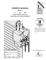
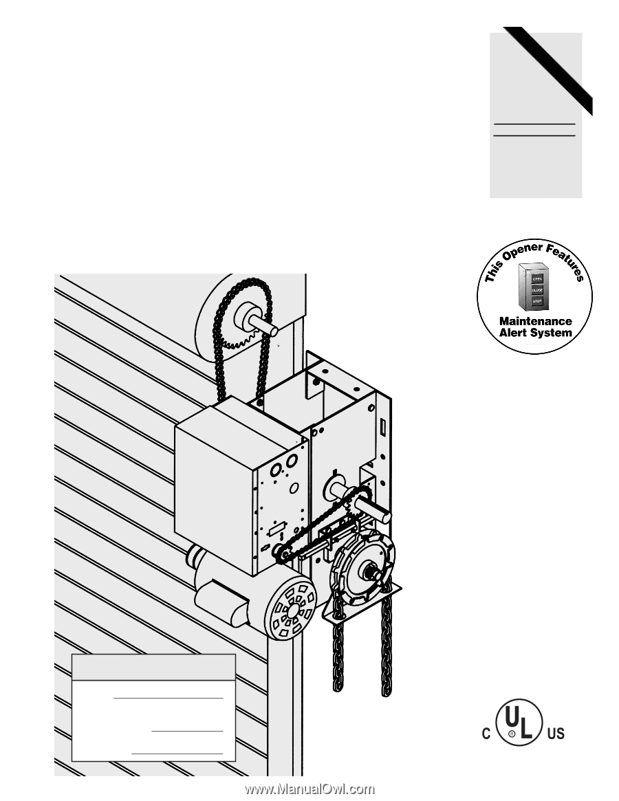
OWNER'S MANUAL MODELS: J ✦ H ✦ HJ LOGIC CONTROL (VER. 2.0) INDUSTRIAL DUTY DOOR OPERATOR LOGIC LCONTROL FACTORY SET when the opener requires immediate service. 2 YEAR WARRANTY Serial # (located on electrical box cover) Installation Date Wiring Type NOT FOR RESIDENTIAL USE 41B6 LISTED DOOR OPERATOR - LiftMaster H | J VERSION 2 LOGIC Manual - Page 2
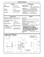
LiftMaster CPSII. WEIGHTS AND DIMENSIONS HANGING WEIGHT: .........80-110 LBS. 14.50" 7.25" 17.63" 14.60" 4.63" 4.41" MOUNTING DIMENSIONS A - Wall Mounting B - Bracket Mounting (rolling door) 7.50" 6.63" A B 5.50" B 1.50" A B 13.75" B 8.00" 7.50" 16.50" Hand Chain Wheel present with Models - LiftMaster H | J VERSION 2 LOGIC Manual - Page 3
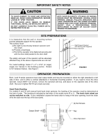
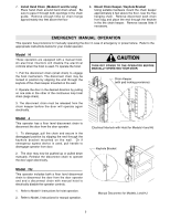
TO DOOR AND OPERATOR, MAKE ALL DOOR LOCKS INOPERATIVE. SECURE LOCK(S) IN "OPEN" POSITION. IF THE DOOR LOCK NEEDS TO REMAIN FUNCTIONAL, INSTALL AN INTERLOCK SWITCH. DO NOT CONNECT ELECTRIC POWER UNTIL INSTRUCTED TO DO SO. KEEP DOOR BALANCED. STICKING OR BINDING DOORS MUST BE REPAIRED. DOORS, DOOR - LiftMaster H | J VERSION 2 LOGIC Manual - Page 4
Optimum Distance 12 - 15" Optimum Distance 12 - 15" Typical Right Hand Wall Mounted Operator FIGURE 3 IMPORTANT: The shelf or bracket must provide adequate support, prevent play between operator and door shaft, and permit operator to be fastened securely and with the drive shaft parallel to the - LiftMaster H | J VERSION 2 LOGIC Manual - Page 5
HJ Keyhole Bracket Model HJ This operator includes both a floor level disconnect chain to disconnect the door from the door operator and and a disconnect chain with manual hoist to electrically disable the operator controls. 1. Refer to Model H instructions for hoist operation. 2. Refer to Model - LiftMaster H | J VERSION 2 LOGIC Manual - Page 6
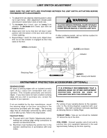
open (N.O.) output are compatible with your operator. This includes pneumatic and electric edges. If your door does operator. If not pre-installed by the door manufacturer, mount the sensing edge on the door according to the instructions provided with the edge. The sensing edge may be electrically - LiftMaster H | J VERSION 2 LOGIC Manual - Page 7
SUPPLY GROUND WIRE. FAILURE TO PROPERLY GROUND THIS UNIT COULD RESULT IN ELECTRIC SHOCK AND SERIOUS INJURY. TO AVOID DAMAGE TO DOOR AND OPERATOR, MAKE ALL DOOR LOCKS INOPERATIVE. SECURE LOCK(S) IN "OPEN" POSITION. IF THE DOOR LOCK NEEDS TO REMAIN FUNCTIONAL, INSTALL AN INTERLOCK SWITCH. CAUTION ON - LiftMaster H | J VERSION 2 LOGIC Manual - Page 8
On all models with type B2 control wiring, a terminal bracket marked R1 R2 R3 is located on the outside of the electrical enclosure. All standard radio control receivers WARNING (single channel residential type) may be mounted to this bracket. The operator will then open a fully closed door, close - LiftMaster H | J VERSION 2 LOGIC Manual - Page 9
until there is just enough tension to permit the operator to move the door smoothly but to allow the clutch to slip if the door is obstructed. When the clutch is properly adjusted, it should generally be possible to stop the door by hand during travel. CAUTION: The adjustable friction clutch is NOT - LiftMaster H | J VERSION 2 LOGIC Manual - Page 10
LOGIC CONTROL (VER. 2.0) 1 PHASE WIRING DIAGRAM 1837-1 MOTOR 115V 1 PHASE MOTOR 230V 1 PHASE TO REVERSE MOTOR DIRECTION 115 VOLT: REVERSE BLUE AND YELLOW WIRES. 208-230 VOLT: REVERSE PURPLE AND GRAY WIRES. 10 - LiftMaster H | J VERSION 2 LOGIC Manual - Page 11
LOGIC CONTROL (VER. 2.0) 3 PHASE WIRING DIAGRAM 1837-3 MOTOR 230V 3 PHASE MOTOR 380/460V 3 PHASE TO REVERSE MOTOR DIRECTION REVERSE PURPLE AND GRAY WIRES 11 - LiftMaster H | J VERSION 2 LOGIC Manual - Page 12
STANDARD POWER & CONTROL CONNECTION DIAGRAM Logic Control Board (VER. 2.0) - 115V, 208, 230V, 1Ph 12 - LiftMaster H | J VERSION 2 LOGIC Manual - Page 13
STANDARD POWER & CONTROL CONNECTION DIAGRAM Logic Control Board (VER. 2.0) - 208, 230V, 380V, 460V, 3Ph 13 - LiftMaster H | J VERSION 2 LOGIC Manual - Page 14
SETTINGS Logic Control Pushbuttons Open, Close, Stop Open, Close and Stop buttons are mounted directly on the Logic Control board. This will provide easy programming ability and door control at the electrical box. Programmable Maximum Run Timer: Any time a "closing" or "opening" door takes 10 - LiftMaster H | J VERSION 2 LOGIC Manual - Page 15
PCB BOARD ILLUSTRATION RPM LEARN BUTTON HEAT SINK POWER WIRING TERMINAL BLOCK DIP SWITCH CONTROL WIRING TERMINAL BLOCK OPEN, CLOSE, STOP BUTTON 15 - LiftMaster H | J VERSION 2 LOGIC Manual - Page 16
clutch slippage. External interlocks and auxiliary devices. Open button override while door is traveling down. NOTE: Open, Close, and Stop buttons are located on the Logic Control board. This will provide programming ability and door control at the electrical box. WIRING TYPE STATION C2 3 Button - LiftMaster H | J VERSION 2 LOGIC Manual - Page 17
mounting wiring types: These wiring types require the use of self monitoring sensing devices. (The optional Lift Master CPSII photoeye package) TYPE STATION C2 Failsafe 3 Button, 3 Button Radio Control ON Same functions as C2. Failsafe safety device must be installed to operate door LiftMaster - LiftMaster H | J VERSION 2 LOGIC Manual - Page 18
following diagnostic codes are reset except in the case where the Motor or Logic Control board has been replaced and only if the motor doesn't have a start switch. Set unit to any normal mode, B2 is suggested. Begin with the door in the open or closed position. Set the limit switches so the operator - LiftMaster H | J VERSION 2 LOGIC Manual - Page 19
tension Fasteners Check & tighten as required Manual Disconnect Check & Operate Bearings & Shafts Check for wear & operation. I Do not lubricate clutch or V-belt. I Inspect and service whenever a malfunction is observed or suspected. I CAUTION: BEFORE SERVICING, ALWAYS DISCONNECT OPERATOR - LiftMaster H | J VERSION 2 LOGIC Manual - Page 20
ILLUSTRATED PARTS - ELECTRICAL BOX S6 S5 S3 S7 S2 S1 S8 S4 S9 6 7 8 L5 L8 2 L6 L2 5 L3 L1 4 L7 L3 L8 L9 4 5 1 3 L2 L6 L4 9 10 20 - LiftMaster H | J VERSION 2 LOGIC Manual - Page 21
Assy Service Kit, LH Model J and RIght Hand Model H to use right hand assembly, Left hand Model H to use left hand assembly, Model HJ requires both assemblies Brake Kits (Optional) 71-B120 115V Model 71-B240 230-460V Model 71-B120H 115V Model H 71-B240H 230-460V Model H * COMPLETE ELECTRICAL - LiftMaster H | J VERSION 2 LOGIC Manual - Page 22
ILLUSTRATED PARTS - Model J 5 6 7 1 8 9 C8 C20 C10 C9 D1 D7 D4 D8 D11 D3 C21 D10 D9 D2 D5 D6 C4 C6 C24 C7 C16 C23 C17 C14 C18 - LiftMaster H | J VERSION 2 LOGIC Manual - Page 23
-12558 RIGHT HAND DISCONNECT ASSY KIT ITEM D1 D2 D3 D4 D5 D6 D7 D8 D9 D10 D11 PART # 10-10707 10-10708 10-10875 10-10898 11-10878 19-8A-12 82-HN25-12 82-SH10-14 84-FN-10 84-FN-25 86-RP04-100 DESCRIPTION QTY Disconnect Support Bracket 1 Yoke 1 Disconnect - LiftMaster H | J VERSION 2 LOGIC Manual - Page 24
ILLUSTRATED PARTS - Model H 5 6 7 1 D1 D10 D7 D4 D9 8 D8 D11 D3 C12 D2 D5 D6 C15 C6 C2 C17 C5 C16 C4 C18 C7 C19 C18 C25 C19 - LiftMaster H | J VERSION 2 LOGIC Manual - Page 25
-12560 LEFT HAND DISCONNECT ASSY KIT ITEM D1 D2 D3 D4 D5 D6 D7 D8 D9 D10 D11 PART # 10-10707 10-10708 10-10875 10-10898-L 11-10878 19-8A-12 82-HN25-12 82-SH10-14 84-FN-10 84-FN-25 86-RP04-100 DESCRIPTION QTY Disconnect Support Bracket 1 Yoke 1 Disconnect - LiftMaster H | J VERSION 2 LOGIC Manual - Page 26
ILLUSTRATED PARTS - MODEL HJ 26 8 5 6 1 7 L1 L7 L4 L10 L9 L8 L11 L3 C17 L2 L5 L6 C7 C2 C20 C6 C5 C22 C23 C30 C14 C19 O10 O5 - LiftMaster H | J VERSION 2 LOGIC Manual - Page 27
REPLACEMENT PARTS KITS - MODEL HJ LOGIC CONTROL (VER. 2.0) Refer to the parts lists below for replacement kits available for your operator. If optional modifications and/or accessories are included with your operator, certain components may be added or remove from these lists. Individual - LiftMaster H | J VERSION 2 LOGIC Manual - Page 28
Close 1 BUTTON STATION OR ANY AUXILIARY DEVICE OPEN / CLOSE 14 B2, T & TS MODE ONLY Open Open D1 & E2 MODE ONLY Close Close RESIDENTIAL RADIO CONTROLS OPEN / CLOSE 4 1 10 RADIO CONTROL (24VDC ONLY) SENSING DEVICE TO REVERSE OR STOP 11 8 EXTERNAL INTERLOCK Remove Jumper When Interlock is - LiftMaster H | J VERSION 2 LOGIC Manual - Page 29
DEPRESS PLATE OPEN LIMIT SW. ROTATOR CUP RPM BOARD SAFETY LIMIT SW. 40-14329B ELECTRICAL BOX END VIEW LIMIT NUT Note: 1) See Owner's Manual for Dip Switch Functions and Programming Procedures 2) TO REVERSE MOTOR DIRECTION: INTERCHANGE PURPLE AND GRAY WIRES AT CONTACTOR #1 & 3. OPERATING MODES - LiftMaster H | J VERSION 2 LOGIC Manual - Page 30
Logic Control (Ver. 2) 575 VOLT THREE PHASE W/ CONTACTOR 1897 DIP SWITCH SETTINGS PROGRAM SETTINGS ON MAX RUN TIMER 1 2 3 4 ON MOTOR DIRECTION: INTERCHANGE PURPLE AND GRAY WIRES AT CONTACTOR. CLOSE LIMIT SW. ROTATOR CUP DEPRESS PLATE OPEN LIMIT SW. ON C2 FAIL SAFE 1 2 3 4 ON B2 FAIL SAFE 1 2 - LiftMaster H | J VERSION 2 LOGIC Manual - Page 31
ADDENDUM 575 Volt Logic 2 Operator MODELS: T and SD NOTE: Refer to addendum for Wiring Diagram and Electrical Box Replacement Parts, for all other installation instructions refer to owners manual shipped with operator. 575 VOLT THREE PHASE W/ CONTACTOR - LiftMaster H | J VERSION 2 LOGIC Manual - Page 32
ILLUSTRATED PARTS - ELECTRICAL BOX S6 S5 S2 7 2 S7 S1 S8 S4 S9 5 L3 L1 6 S3 L7 L9 L5 L8 L6 L2 L8 4 8 9 L2 L6 L4 10 1 3 3
-
 1
1 -
 2
2 -
 3
3 -
 4
4 -
 5
5 -
 6
6 -
 7
7 -
8
-
9
-
10
-
11
-
12
-
13
-
14
-
15
-
16
-
17
-
18
-
19
-
20
-
21
-
22
-
23
-
24
-
25
-
26
-
27
-
28
-
29
-
30
-
31
-
32
 |
 |
OWNER'S MANUAL
MODELS:
J
✦
H
✦
HJ
LOGIC CONTROL (VER. 2.0)
INDUSTRIAL DUTY DOOR OPERATOR
Serial #
(located on electrical box cover)
Installation Date
Wiring Type
2
YEAR
WARRANTY
LOGIC CONTROL
L
C2 Wiring
FACTORY SET
See pages 16 thru 18
for other wiring
configurations
The Maintenance Alert System
allows the installer to set an internal
Maintenance Cycle Counter.
An LED
on the 3-button station will signal when
the set number of cycles is reached or
when the opener requires immediate
service.
TM
PATENT PENDING
NOT FOR RESIDENTIAL USE
LISTED
DOOR
OPERATOR
41B6