LiftMaster H J VERSION 2 LOGIC Manual - Page 8
Install Control Station
 |
View all LiftMaster H manuals
Add to My Manuals
Save this manual to your list of manuals |
Page 8 highlights
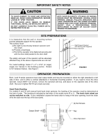
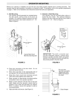
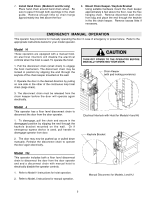
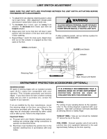
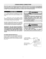
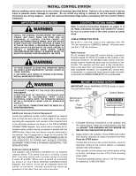
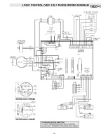
INSTALL CONTROL STATION Before installing control station be sure to follow all warnings described below. Failure to do so may result in severe injury to persons and/or damage to operator. Do not install any wiring or attempt to run the operator without consulting the wiring diagram. Install the optional Reversing Edge before proceeding with the Control Station installation. IMPORTANT SAFETY NOTES WARNING INSTALL THE CONTROL STATION WHERE THE DOOR IS VISIBLE, BUT AWAY FROM THE DOOR AND ITS HARDWARE. IF CONTROL STATION CANNOT BE INSTALLED WHERE DOOR IS VISIBLE, OR IF ANY DEVICE OTHER THAN THE CONTROL STATION IS USED TO ACTIVATE THE DOOR, A REVERSING EDGE MUST BE INSTALLED ON THE BOTTOM OF THE DOOR. FAILURE TO INSTALL A REVERSING EDGE UNDER THESE CAUTION CIRCUMSTANCES MAY RESULT IN SERIOUS INJURY OR DEATH TO PERSONS TRAPPED BENEATH THE DOOR. WARNING TO AVOID DAMAGE TO DOOR AND OPERATOR, MAKE ALL DOOR LOCKS INOPERATIVE. SECURE LOCK(S) IN "OPEN" POSITION. IF THE DOOR LOCK NEEDS TO REMAIN FUNCTIONAL, INSTALL AN INTERLOCK SWITCH. CONTROL STATION WIRING Refer to Control Connection Diagrams on pages 11 & WARNING 24. Make connection through hole labeled for control. Do not run control wires in the same conduit as power wires. CABLE CONNECTION NOTE: Be sure to use the control box opening with the 7/8" dia. knockout for CONTROL cable(s). All power wires use the 1-1/16" dia. knockout. Radio ControlsWARNING On all models with type B2 control wiring, a terminal bracket marked R1 R2 R3 is located on the outside of the electrical enclosure. All standard radio control receivers WARNING (single channel residential type) may be mounted to this bracket. The operator will then open a fully closed door, close a fully open door, and reverse a closing door from the radio transmitter. However, for complete door control from a transmitter, a commercial three-channel radio set (with connections for OPEN/CLOSE/STOP) is recommended. RNING CWAAURTNIOINNG UTION DISCONNECT POWER AT THE FUSE BOX BEFORE PROCEEDING. OPERATOR MUST BE PROPERLY GROUNDED AND CONNECTED IN ACCORDANCE WITH LOCAL ELECTRICAL CODES. NOTE: THE OPERATOR SHOULD BE ON A SEPARATE FUSED LINE OF ADEQUATE CAPACITY. ALL ELECTRICAL CONNECTIONS MUST BE MADE BY A QUALIFIED INDIVIDUAL. WARNING MOUNT WARNING NOTICE WARNING IMPORTANT: Mount WARNING NOTICE beside or below the push button station. Control Station Maintenance Alert LED Push Buttons OPEN CLOSE WARNING TO PREVENT ENTRAPMENT DO NOT START DOOR DOWNWARD UNLESS DOORWAY IS CLEAR Additional Access Control Equipment Locate any additional access control equipment as desired (but so that the door will be in clear sight of the person operating the equipment), and connect to the terminal block in the electrical enclosure as shown on the FIELD WIRING CONNECTIONS diagram. Any control with a normally (N.O.) isolated output contact may be connected in parallel with the OPEN button. More than one device may be connected in this manner. Use 16 gauge wire or larger for all controls. DO NOT USE THE CONTROL CIRCUIT TRANSFORMER (24VAC) IN THE OPERATOR TO POWER ANY ACCESS CONTROL EQUIPMENT OTHER THAN A STANDARD RESIDENTIAL TYPE RADIO RECEIVER. External Interlock Switch The operator has a terminal connection for an external interlock switch. This switch must be a normally closed (N.C.) two-wire device with a contact rating of at least 3 amps @ 24VAC. When such a switch is connected as shown on the FIELD WIRING CONNECTIONS diagram, the control circuit will be disabled when the switch is actuated, thereby preventing electrical operation of the door from the control devices. 8 WARNING Notice 1. Complete electrical connections to the operator and the control station. Fasten the control station to the wall and MOUNT THE WARNING NOTICE BESIDE OR BELOW THE PUSH BUTTON STATION. 2. Apply power to the operator. Press OPEN push button and observe direction of trolley movement and then Press the STOP button. If trolley did not move in the correct direction, check for improper wiring at the control station or between operator and control station. If the operator is three phase and control station wiring is correct, exchange any two of the three incoming power leads. If electrical problems persist, call our Toll Free number for assistance (1-800-528-2806).
-
 1
1 -
2
-
 3
3 -
 4
4 -
 5
5 -
 6
6 -
 7
7 -
 8
8 -
 9
9 -
 10
10 -
 11
11 -
 12
12 -
 13
13 -
14
-
15
-
16
-
17
-
18
-
19
-
20
-
21
-
22
-
23
-
24
-
25
-
26
-
27
-
28
-
29
-
30
-
31
-
32
 |
 |
