LiftMaster H J (CUBE STYLE) Manual - Page 7
Power Wiring Connections, POWER WIRING
 |
View all LiftMaster H manuals
Add to My Manuals
Save this manual to your list of manuals |
Page 7 highlights
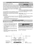
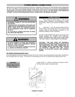
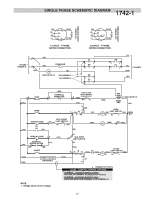
POWER WIRING CONNECTIONS Remove the cover from the electrical enclosure. Inside this enclosure you will find the wiring diagram(s) for your unit. Refer to the diagram (glued on the inside of the cover) for all connections described below. If this diagram is missing, call the number on the back of this manual. DO NOT INSTALL ANY WIRING OR ATTEMPT TO RUN THIS OPERATOR WITHOUT CONSULTING THE WIRING DIAGRAM. RNING WARNING UTION DISCONNECT POWER AT THE FUSE BOX BEFORE PROCEEDING. OPERATOR MUST BE PROPERLY GROUNDED AND CONNECTED IN ACCORDANCE WITH LOCAL ELECTRICAL CODES. NOTE: THE OPERATOR SHOULD BE ON A SEPARATE FUSED LINE OF ADEQUATE CAPACITY. WARNING ALL ELECTRICAL CONNECTIONS MUST BE MADE BY A QUALIFIED INDIVIDUAL. WARNING POWER WIRING 1. Be sure that the power supply is of the correct voltage, phase, frequency, and amperage to supply the operator. Refer to the operator nameplate on the cover. 2. Using the 1-1/16" dia conduit access hole as shown below, bring supply lines to the operator and connect wires to the terminals indicated on the WIRING CONNECTIONS DIAGRAM. DO NOT TURN POWER ON UNTIL YOU HAVE FINISHED MAKING ALL POWER AND CONTROL WIRING CONNECTIONS AND HAVE COMPLETED WARNING THE LIMIT SWITCH ADJUSTMENT PROCEDURE. TO AVOID DAMAGE TO DOOR AND OPERATOR, MAKE ALL DOOR LOCKS INOPERATIVE. SECURE LOCK(S) IN "OPEN" POSITION. IF THE DOOR LOCK NEEDS TO REMAIN FUNCTIONAL, INSTALL AN INTERLOCK SWITCH. CAUTION ON THREE PHASE MACHINES ONLY! CAUTION: THIS UNIT MUST BE PROPERLY GROUNDED. A GROUND SCREW IS SUPPLIED IN THE ELECTRICAL BOX FOR CONNECTION OF THE POWER SUPPLY GROUND WIRE. FAILURE TO PROPERLY GROUND THIS UNIT COULD RESULT IN ELECTRIC SHOCK AND SERIOUS INJURY. WARNING Incorrect phasing of the power supply will cause the motor to rotate in the wrong direction (open when CLOSE button is pressed and vice-versa). To correct this, interchange any two of the incoming three phase power lines. WARNING Do Not Run Power & Control Wiring in the Same Conduit Three (3)7/8" & 1-1/6"dia. knockouts for Power & Control Wiring access (Near & Opposite side) CONDUIT ACCESS 7
-
 1
1 -
 2
2 -
 3
3 -
 4
4 -
 5
5 -
 6
6 -
 7
7 -
 8
8 -
 9
9 -
 10
10 -
 11
11 -
 12
12 -
13
-
14
-
15
-
16
-
17
-
18
-
19
-
20
-
21
-
22
-
23
-
24
 |
 |
