LiftMaster HCTDCU HCTDCU Installation Blueprint Manual - Page 2
Usage Classification, Class II, III, and IV, American Wire, Gauge AWG, Maximum Wire, Length 120 Vac, - model
 |
View all LiftMaster HCTDCU manuals
Add to My Manuals
Save this manual to your list of manuals |
Page 2 highlights
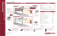
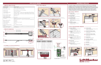
INSTALLATION OVERVIEW OPERATOR SPECIFICATIONS Usage Classification Main AC Supply System Operating Voltage Accessory Power Solar Power Max Variable Operating Lengths (Operator Weights) Maximum Gate/Door Weight Maximum Gate/Door Width (sectional and one-piece) Maximum Gate/Door Height Travel Speed Maximum Daily Cycle Rate Maximum Duty Cycle Operating Temperature Expansion Board Inherent Entrapment Protection (Type A) External Entrapment Protection (Type B1 and/or Type B2) Class II, III, and IV 120 Vac, 4 Amps OR 240 Vac, 2 Amps 24 Vdc Transformer Run / Battery Backup 24 Vdc, 500mA max. for ON + SW (switched) 24 Vdc at 60 watts max. 8 foot (2.4 m) gate - 11.75 foot (3.6 m) operator length (130 lbs. [58.9 kg]) 10 foot (3.1 m) gate - 13.75 foot (4.2 m) operator length (145 lbs. [65.7 kg]) 12 foot (3.7 m) gate - 15.75 foot (4.8 m) operator length (160 lbs. [72.5 kg]) 700 lbs. (317.5 kg) 22 ft. (6.7 m) 12 ft. (3.7 m) BIPART Delay OFF (Default) - 8 inches (20.3 cm) per second BIPART Delay ON (Fast) - 11 inches (27.9 cm) per second (open speed only) Continuous Continuous -20°C to 60°C (-4°F to 140°F) Provided Dual - RPM and Current Sense 3 inputs per board - any combination of up to 3 photoelectric sensors and up to 2 edge sensors OPERATOR DIMENSIONS HCT08: 139" (353 cm) HCT10: 163" (414 cm) HCT12: 187" (475 cm) 23.8" (60.3 cm) MOUNT THE OPERATOR 1. Place the motor unit on packing material to protect the cover. Make sure the header bracket is in the center of the opening. Bolt or weld the header bracket to the wall. Header Bracket Header Bracket 2. Lift the operator and align with center mark on ceiling. Have someone hold the operator in place or use a post as a temporary support. Bolt the operator to the ceiling. (A support post is not part of the operator. Use only for installation.) Concrete Anchor 1/2" x 3 1/2" Brackets (not provided) 3. Bolt or weld arm to gate/door. Temporary Support Post Flush Mount Arm 7.5" (19.1 cm) HCTDCU Door Arm HCTDCU 7.8" (19.9 cm) 4.1" (10.3 cm) 17.5" (44.5 cm) DETERMINE LOCATION FOR OPERATOR 1. With the gate/door closed, mark the center. 2. Open the gate/door and mark the center point on the ceiling. POWER WIRING American Wire Gauge (AWG) Maximum Wire Length (120 Vac) 14 130 feet (39.6 m) 12 205 feet (62.5 m) 10 325 feet (99.1 m) 8 520 feet (158.5 m) 6 825 feet (251.5 m) 4 1312 feet (399.9 m) NOTE: Use copper conductors ONLY. Maximum Wire Length (240 Vac) 260 feet (79.3 m) 410 feet (125 m) 650 feet (198.1 m) 1040 feet (317 m) 1650 feet (502.9 m) 2624 feet (799.8 m) Use UL listed conduit to enclose power wires Input Power Connection GROUND HOT NEUTRAL Green White White Black Red Piggy Back AC Power Switch EMI BOARD ENTRAPMENT PROTECTION This operator contains an inherent (internal) entrapment protection system and REQUIRES the addition of a LiftMaster external monitored entrapment protection system (non-contact photoelectric sensor or contact edge sensor) for EACH entrapment zone prior to gate movement. An entrapment zone is every location or point of contact where a person can become entrapped between a moving gate and a stationary object. Your application may contain one or many entrapment zones. System includes six monitored entrapment protection inputs capable of covering all entrapment zones. Use only LiftMaster approved entrapment protection devices. NON-CONTACT SENSORS Model LMTBU LiftMaster Monitored Through Beam Photoelectric Sensor Model LMRRU LiftMaster Monitored Retro-Reflective Photoelectric Sensor Model CPSUN4G LiftMaster Monitored Through Beam Photoelectric Sensor NOTE: CPSUN4G is provided with the operator Model CPS-OPEN4 LiftMaster Monitored Dual-Sided Photoelectric Sensor CONTACT SENSORS (EDGE SENSORS) Model LMWEKITU LiftMaster Monitored Wireless Edge Kit (Transmitter and Receiver) Model L50, L504AL, L505AL, and L506AL Large Profile Monitored Edge (82 ft. roll) Aluminum Channel (4 ft., 5 ft., 6 ft.) Model L50E Large Profile Ends Kit (10 pairs) Model S50, S504AL, S505AL, and S506AL Small Profile Monitored Edge (82 ft. roll) Aluminum Channel (4 ft., 5 ft., 6 ft.) Model S50E Small Profile Ends Kit (10 pairs) Model L50CHP PVC Channel for Both Large and Small Profiles (8 ft., pack of 10) Model L50CHAL Aluminum Channel for Both Large and Small Profiles (10 ft., pack of 8) Models WS4, WS5, and WS6 Wraparound Square Monitored Edge (4 ft., 5 ft., 6 ft.) Models WR4, WR5, and WR6 Wraparound Round Monitored Edge (4 ft., 5 ft., 6 ft.) Model ETOOL Cutting Tool for Edge Material OES-SD16, OES-SD24 Optical Edge System for Overhead Doors (16 ft., 24 ft.) OES-4504 PVC Channel (1-3/4" x 1-3/4") OES-5104 PVC Channel (2" x 2") Power Wiring Connector Power Wiring Sockets (120 Vac factory default)
-
 1
1 -
 2
2
 |
 |
