LiftMaster HS670 HS670 GL BOARD Manual - Page 9
Installation, Drive Rail, Operator Mounting, Concrete Pad
 |
View all LiftMaster HS670 manuals
Add to My Manuals
Save this manual to your list of manuals |
Page 9 highlights
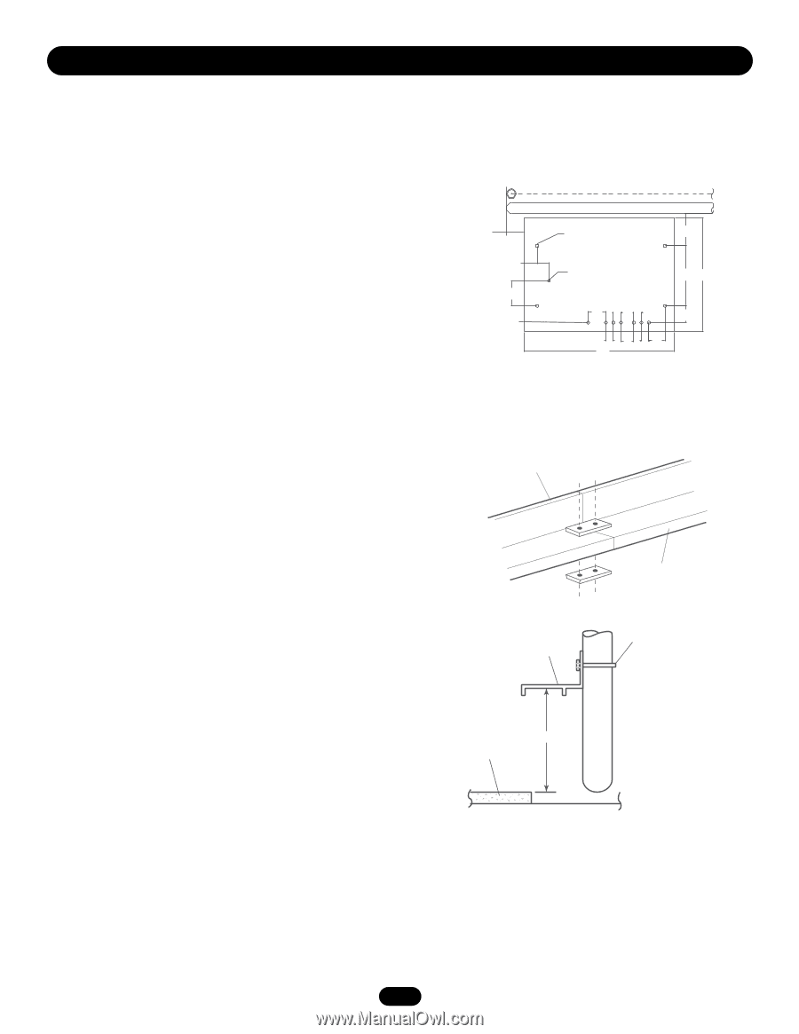
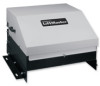
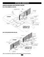
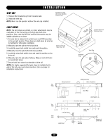
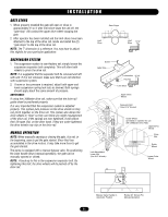
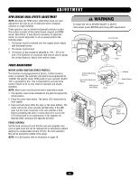
I N S TA L L AT I O N NOTES: Installation shown is for a right-handed unit (on right side of gate opening when inside looking out). Left-handed is opposite. For left-handed conversion, see page 17. If there is suitable existing concrete at area of unit mounting, use dimensioning procedure described in step 1. Conduit locations may require modifications to suit your application. CONCRETE PAD 1. Layout concrete pad as detailed. 2. Locate conduit, as required, prior to pouring concrete. 3 Pour concrete pad. The pad must be level and above the ground line. Pad must be a minimum of 24" in depth or below the frost line, whichever is greater. 4. Allow concrete to set at least 2 days before installing unit. 5. Locate (4) 1/2" concrete anchors (not provided) or other means of fastening as shown. Anchors must be positioned accurately and secure in the concrete. NOTE: Always use separate conduits for power wiring and control wiring.You may want to install extra conduit for future wiring considerations. For detailed information on the emergency disconnect system, see instructions provided with it. This is only a suggested layout, other pad layouts are possible. DRIVE RAIL 1. Mark the location to install drive rail 11-1/2" from the top of concrete pad. The drive rail should be the gate opening width plus 3' to 4'. The drive rail must be level and parallel to the gate and operator. 2. Fasten the drive rail securely to the gate and backframe. IMPORTANT NOTE: Make sure that the drive rail and wheels are aligned properly. OPERATOR MOUNTING 1. Remove cover by loosening bolts on each side of cover and remove bolt from the front of the cover. Lift cover off. 2. Secure operator to the concrete pad using (4) 1/2" concrete anchors (not provided) with the drive wheels facing the gate. The operator must be level and parallel with the gate and drive rail. NOTE: Loosen the bolts that secure the mounting legs to the unit. The distance between the operator and the rail can then be slightly adjusted. After adjustment, retighten the bolts. "Gate" Shown Open As Required Anchor Location Marked "Z" Z +7.5 Z 2.75 Optional Emergency Disconnect 14.0 26.5 5.88 Z Power Conduit Entrance 4.13 1.75 1.75 Z 3.88 3.0 1.75 1.753.75 +=Critical Dimension 35.0 Drive Rail Section To Attach Drive Rails Together: Optional Drive Rail Drive Rail Section Mounting Hardware By Others 11-1/2" Pad 9
-
 1
1 -
2
-
3
-
 4
4 -
 5
5 -
 6
6 -
 7
7 -
 8
8 -
 9
9 -
 10
10 -
 11
11 -
 12
12 -
 13
13 -
 14
14 -
15
-
16
-
17
-
18
-
19
-
20
-
21
-
22
-
23
-
24
-
25
-
26
-
27
-
28
-
29
-
30
-
31
-
32
-
33
-
34
-
35
-
36
 |
 |