LiftMaster LA400DC LA400DC Owner's Manual
LiftMaster LA400DC Manual
 |
View all LiftMaster LA400DC manuals
Add to My Manuals
Save this manual to your list of manuals |
LiftMaster LA400DC manual content summary:
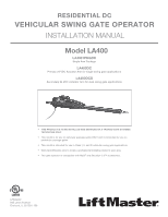
- LiftMaster LA400DC | LA400DC Owner's Manual - Page 1
- LiftMaster LA400DC | LA400DC Owner's Manual - Page 2
- LiftMaster LA400DC | LA400DC Owner's Manual - Page 3
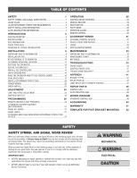
34 ERROR CODES 34 CONTROL BOARD LEDS 37 TROUBLESHOOTING CHART 38 APPENDIX 41 BRACKET TYPES 41 SOLAR PANEL(S 42 LIMIT SETUP WITH A REMOTE CONTROL 47 REPAIR PARTS 48 CONTROL BOX 48 GATE OPERATOR ARM 48 WIRING DIAGRAM 49 STANDARD CONTROL BOX 49 ACCESSORIES 50 WARRANTY - LiftMaster LA400DC | LA400DC Owner's Manual - Page 4
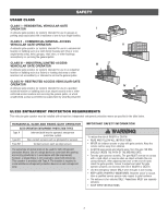
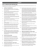
AND FOLLOW ALL INSTRUCTIONS. • NEVER let children operate or play with gate controls. Keep the remote control away from children. • ALWAYS keep people and objects away from the gate. NO ONE SHOULD CROSS THE PATH OF THE MOVING GATE. • Test the gate operator monthly. The gate MUST reverse on contact - LiftMaster LA400DC | LA400DC Owner's Manual - Page 5
. Swinging gates shall not open into public access areas. 7. The gate must be properly installed and work freely in both directions prior to the installation of the gate operator. 8. Controls intended for user activation must be located at least 6 feet (1.8 m) away from any moving part of the gate - LiftMaster LA400DC | LA400DC Owner's Manual - Page 6
Class 1, Class II and Class III vehicular horizontal swing gates: 4.1.1 Gates shall be designed, constructed and installed so as not to create an entrapment area between the gate and the supporting structure or other fixed object when the gate moves toward the fully open position, subject to the - LiftMaster LA400DC | LA400DC Owner's Manual - Page 7
50-19503) If your application requires the gate to be pushed open, a push-to-open bracket is required (refer to accessories). Expansion Board (Model K1D8080-1CC) Large Metal Control Box for Solar Applications (Model XLSOLARCONTDC) Required for solar installations (batteries not included). Requires - LiftMaster LA400DC | LA400DC Owner's Manual - Page 8
model is intended for use in vehicular swing gate applications: Usage Classification Main AC Supply System Operating Voltage Accessory Power Solar Power Max Maximum Gate Dual - RPM and Current Sense 3 inputs per board .2 lbs. (6 kg.) Standard Control Box Large Metal Control Box 16-7/16" (41.8 cm) - LiftMaster LA400DC | LA400DC Owner's Manual - Page 9
Warning Signs CHECK YOUR GATE Gate MUST be level. Gate and gate post MUST be plumb. Gate MUST have a smooth bottom edge, no protrusions should exist. Remove ANY/ALL wheels from the bottom of gate. Gate MUST NOT hit or drag across ground. Gate MUST swing freely and be supported entirely by its - LiftMaster LA400DC | LA400DC Owner's Manual - Page 10
Rod Check national and local codes for proper depth Photoelectric Sensors DUAL GATE Secondary Operator Warning Sign Edge Sensor Junction Box Photoelectric Sensors Warning Sign Primary Operator Control Box Photoelectric Sensors Photoelectric Sensors Edge Sensor Water Tight Conduit (Not - LiftMaster LA400DC | LA400DC Owner's Manual - Page 11
gate to prevent access through openings anywhere the gate may travel. • Mount controls at least 6 feet (1.8 m) from the gate or ANY moving part of the gate. • Install Warning signs on EACH side of gate swing gate. Non-contact sensors such as photoelectric sensors MUST be mounted across the gate - LiftMaster LA400DC | LA400DC Owner's Manual - Page 12
the lock on the release lever and turn it 180° counterclockwise. 2. Turn the release lever 180° counterclockwise. The operator is now in manual mode. 3. Assemble gate post bracket by placing pull-to-open bracket on top of post bracket. 4. Insert the bolt through both brackets and secure with washer - LiftMaster LA400DC | LA400DC Owner's Manual - Page 13
greater than 4" (10.2 cm) entrapment protection for this area is required. TEMPLATE METHOD 1. Close the gate. 2. Place the template (provided on the back page of this manual) under the center of the gate hinge point. 3. Use a screwdriver or dowel rod to temporarily mark the location in front of the - LiftMaster LA400DC | LA400DC Owner's Manual - Page 14
and secure with washer, lock washer and nut. Screwdriver 1 TEST GATE TRAVEL NOTE: If gate does not open and close completely adjust the position of the gate bracket and mark new mounting holes. 1. Manually open and close the gate. 2. Ensure that the operator does not bind against the pull-to - LiftMaster LA400DC | LA400DC Owner's Manual - Page 15
for the post bracket. Remove the clamp and the operator, set aside. 2. Drill adequate holes in the gate post. 3. Secure the post bracket to the gate post using hardware. GATE BRACKET The gate operator (arm) must be level. Some installations may require additional reinforcement be installed on the - LiftMaster LA400DC | LA400DC Owner's Manual - Page 16
5 INSTALL THE CONTROL BOX For Large Metal Control Box installation, refer to the following page. STANDARD CONTROL BOX The control box MUST be mounted within 5 feet (1.52 m) of the gate operator. Mount the control box as high as possible for best radio reception. Make sure the control box is level - LiftMaster LA400DC | LA400DC Owner's Manual - Page 17
THE CONTROL BOX LARGE METAL CONTROL BOX (XLSOLARCONTDC) The control box MUST be mounted within 5 feet (1.52 m) of the gate operator. Mount the control box as high as possible for best radio reception. Make sure the control box is level. WALL OR COLUMN MOUNT 1. Open the control box. The control box - LiftMaster LA400DC | LA400DC Owner's Manual - Page 18
be returned to service. • Disconnect power at the fuse box BEFORE proceeding. control box) STEP 7 WIRE THE OPERATOR ARM TO THE CONTROL BOARD 1. Choose a knockout in the bottom of the control box 6 Plug the connector into the GATE 1 terminal on the control board as shown. 7. Tighten the connector - LiftMaster LA400DC | LA400DC Owner's Manual - Page 19
than wireless applications. Wireless dual gates will require the installation of two control boxes, one for each operator arm. OPEN CLOSE STOP WIRELESS DUAL GATES INSTALL A SECOND OPERATOR ARM AND CONTROL BOX Install a second operator arm and control box by following installation steps 1-7. TO - LiftMaster LA400DC | LA400DC Owner's Manual - Page 20
STEP 8 continued... DUAL GATES ONLY WIRED DUAL GATES INSTALLATION INSTALL A SECOND OPERATOR ARM Install a second operator arm by following installation steps 1-4. INSTALL THE EXTENSION CABLE AND JUNCTION BOX Before digging, contact local underground utility locating companies. 1. Trench across - LiftMaster LA400DC | LA400DC Owner's Manual - Page 21
STEP 8 continued... DUAL GATES ONLY WIRED DUAL GATES INSTALLATION WIRE THE SECONDARY OPERATOR ARM TO THE CONTROL BOARD 1. Choose a knockout in the bottom of the control box. 2. Insert the extension cable through the watertight connector. 3. Insert the extension cable and watertight connector into - LiftMaster LA400DC | LA400DC Owner's Manual - Page 22
obligated to test entrapment protection devices monthly. NON-CONTACT SENSORS If the photoelectric sensor beam gets blocked while the gate is moving, the gate will stop and reverse for 4 seconds. The gate will not be able to travel in that direction until the obstruction is cleared. CPS-UN4 or CPS - LiftMaster LA400DC | LA400DC Owner's Manual - Page 23
Refer to the wiring diagram or the specific entrapment protection device manual for more information. These entrapment protection device inputs are for for the close direction. When an obstruction is sensed during gate closing the gate will open to the full open position and resets the Timer - LiftMaster LA400DC | LA400DC Owner's Manual - Page 24
reviewed for suitability of wire installation. 1. Turn off the AC power from the main power source circuit breaker. 2. Run the AC power wires to the control box. 3. Remove the junction box box cover. Ensure the wires are not pinched. 8. Plug the J15 plug into the control board. The control board - LiftMaster LA400DC | LA400DC Owner's Manual - Page 25
lever clockwise 180° back to the engaged position. This engages the motor. The illustration shows the release lever in the engaged position. 2. Turn the gate. The force is adjusted automatically when you program the limits but should be fine tuned using the REVERSAL FORCE dial on the control board ( - LiftMaster LA400DC | LA400DC Owner's Manual - Page 26
switch to the 2 position and repeat steps 2-7. When limits are set properly the operator will automatically exit limit setting mode. * Dual Gates ONLY: When the limits are set on the secondary gate first the control board will not exit the limit setting mode until the limits are set on the primary - LiftMaster LA400DC | LA400DC Owner's Manual - Page 27
continued... FINE TUNE THE FORCE The REVERSAL FORCE DIAL on the control board is used for fine tuning the force in cases where wind or environmental changes may affect the gate travel. Based on the length and weight of the gate it may be necessary to make additional force adjustments. The force - LiftMaster LA400DC | LA400DC Owner's Manual - Page 28
remote control buttons, repeat the programming steps above. NOTICE: To comply with FCC and/or Industry Canada (IC) rules, adjustment or modifications of this transceiver are prohibited. THERE ARE NO USER SERVICEABLE PARTS. Any changes or modifications not expressly approved by the party responsible - LiftMaster LA400DC | LA400DC Owner's Manual - Page 29
the LiftMaster Internet Gateway: USING THE LEARN BUTTON ON THE OPERATOR'S CONTROL BOARD 1. Connect the ethernet cable to the LiftMaster (exiting learn limit mode). 6. Ensure gate is closed. 7. Give the operator an OPEN command. 8. Within 30 seconds, when the gate is at the open limit press and - LiftMaster LA400DC | LA400DC Owner's Manual - Page 30
Critically low battery is less than 23 V 5 BIPART DELAY Switch: The LOCK/BIPART DELAY switch is used only for dual gates. See Bipart Delay section. 6 LEARN Button: The LEARN button is for programming remote controls and the network. 7 TIMER-TO-CLOSE dial: The TIMER-TO-CLOSE (TTC) dial can be set to - LiftMaster LA400DC | LA400DC Owner's Manual - Page 31
closed manually. ENGAGE 1. Turn the release lever clockwise 180°. This engages the motor. 2. Turn the key clockwise 180°. This locks the release lever. 3. Remove the key and store in a safe place. The operator is now engaged. RESET BUTTON The reset button is located on the side of the control box - LiftMaster LA400DC | LA400DC Owner's Manual - Page 32
is in the closed position, activation of the remote control button will open the gate. During the open cycle another activation of the remote control will stop the gate and the next activation of the remote control will close the gate. When the gate is in the open position, activation of the remote - LiftMaster LA400DC | LA400DC Owner's Manual - Page 33
when loop is on the outside of the gate. • Holds open gate at open limit • Stops and reverses a closing gate to open limit • Pauses Timer-to-Close at OPEN limit, activates quick close and anti-tailgate features when enabled on the expansion board (control board) Exit Com Shadow Com Interrupt Com - LiftMaster LA400DC | LA400DC Owner's Manual - Page 34
locks Relay activates prior to motor activation and during motor run. Relay is off when motor is off. NOTE: For AC power install a Siemens S10K30 MOV (Metal Oxide Varistor) or equivalent. For DC power install a 1N4005 diode or equivalent. (control board) Maglock (control board) 1N4005 diode or - LiftMaster LA400DC | LA400DC Owner's Manual - Page 35
control board and DOES NOT turn off battery power. ALWAYS disconnect the batteries to service the operator. DESCRIPTION TASK Entrapment Protection Devices Warning Signs Manual Release Gate LiftMaster part 29-NP712 for replacement batteries. The standard control box comes with two 7AH batteries. 33 - LiftMaster LA400DC | LA400DC Owner's Manual - Page 36
power (AC or solar and battery) BEFORE installing or servicing operator. For continued protection against fire: • Replace ONLY with fuse of same type and rating. ERROR CODES NOTE: When cycling or disconnecting power (ac/dc) to the control board, it is recommended that you unplug the J15 plug - LiftMaster LA400DC | LA400DC Owner's Manual - Page 37
TROUBLESHOOTING Was the control board just replaced loop (SHORT or OPEN - LiftMaster Plug-in Loop Detector only Arm 2) Check yellow pass-point wiring. If limits are not accurate, reprogram. Rarely, may be standard operation. Brownout occurred AC/DC board supply dipped below allowable level. Review - LiftMaster LA400DC | LA400DC Owner's Manual - Page 38
TROUBLESHOOTING ERROR CODES continued... Some errors are saved in the board) 80 Close input (EYE/EDGE) communication fault (secondary control box) 81 Open input (EYE/EDGE) communication fault (secondary control box) Force reversal (Arm 1) 91 Force reversal (Arm 2) 92 RPM / STALL Reversal (Arm - LiftMaster LA400DC | LA400DC Owner's Manual - Page 39
TROUBLESHOOTING CONTROL BOARD LEDS STATUS LEDS INPUT OFF POWER ON OFF state AC is paused per second) FASTEST BLINK (8 The timer is cancelled blinks per second) GATE OFF MOVING ON The gate is stopped The gate is opening or closing MEDIUM BLINK (1 Operator is in E1 (single blink per - LiftMaster LA400DC | LA400DC Owner's Manual - Page 40
Defective control board d) Replace defective control board Control board powers up, but motor does control board g) Replace defective control board Arm moves, but cannot set correct limits. a) Arm does not extend or retract enough during travel b) Arm is interfering with mounting bracket c) Gate - LiftMaster LA400DC | LA400DC Owner's Manual - Page 41
power or replace batteries a) Review Exit loop detector settings. Adjust board function not controlling gate. a) Defective main board to expansion board wiring b) Incorrect input wiring to expansion board c) Defective expansion board or defective main board a) Check main board to expansion board - LiftMaster LA400DC | LA400DC Owner's Manual - Page 42
TROUBLESHOOTING TROUBLESHOOTING CHART continued... SYMPTOM Maglock not working correctly. POSSIBLE CAUSES to N.O. and COM terminals. Check that Solenoid has power (do not power solenoid from control board accessory power terminals). If shorting lock's NC and COM wires does not activate Solenoid, - LiftMaster LA400DC | LA400DC Owner's Manual - Page 43
BRACKET TYPES PULL-TO-OPEN Left-Hand Gate APPENDIX Right-Hand Gate PUSH-TO-OPEN Left-Hand Gate Right-Hand Gate 41 - LiftMaster LA400DC | LA400DC Owner's Manual - Page 44
. SOLAR USAGE GUIDE The LA400DC has best in class solar performance due to highly efficient electronics that draw very little power while the gate is not in use (standby). Typical System Standby Battery Current Consumption (mA) System Configuration 2.7 mA Main control board draw with no - LiftMaster LA400DC | LA400DC Owner's Manual - Page 45
(S) SOLAR USAGE GUIDE APPENDIX SOLAR ZONES 3 NOT AVAILABLE 2 1 3 2 1 NOT AVAILABLE 1 SOLAR GATE CYCLES PER DAY (SINGLE GATE) BATTERY CURRENT 100 100 100 100 100 100 100 100 100 n/a 61 SOLAR GATE CYCLES PER DAY (DUAL GATE) BATTERY CURRENT DRAW (mA) ZONE 1 (6 Hrs sunlight/day) - LiftMaster LA400DC | LA400DC Owner's Manual - Page 46
, first you will need a 3-button remote control that has been programmed for OPEN, CLOSE, and STOP. Refer to the Programming section. INITIAL LIMITS AND FORCE ADJUSTMENT For dual gate applications the limits will have to be set for each operator. The gate MUST be attached to the operator before - LiftMaster LA400DC | LA400DC Owner's Manual - Page 47
, first you will need a 3-button remote control that has been programmed for OPEN, CLOSE, and STOP. Refer to the Programming section. INITIAL LIMITS AND FORCE ADJUSTMENT For dual gate applications the limits will have to be set for each operator. The gate MUST be attached to the operator before - LiftMaster LA400DC | LA400DC Owner's Manual - Page 48
Harness Antenna Standard Plastic Control Box (with control board) ATC Fuse Kit Includes 20 Amp (1), 15 Amp (2) 2 3 5 1 4 8 6 7 GATE OPERATOR ARM ITEM PART NUMBER DESCRIPTION 3 1 LA400 Primary Arm 2 41ASWG-442SA Release Lever 3 41ASWG-438SA Motor with Limit Switch Harness 4 41ASWG - LiftMaster LA400DC | LA400DC Owner's Manual - Page 49
STANDARD CONTROL BOX WIRING DIAGRAM To protect against fire and electrocution: • DISCONNECT power and battery BEFORE installing or servicing LA40o0pWerIRatINoGr. DIAGRAM PLASTIC E-BOX 4EC7FN-o?:?r??c?o??ntinued protection against fire: Re•fereRnecep: l0a6c-3e69O28NLY with fuse of same type and - LiftMaster LA400DC | LA400DC Owner's Manual - Page 50
board. Model LOOPDETLM LOOP DETECTOR Low power loop detectors mounted and wired separately inside control box. LiftMaster low power accessory. Model LD7LP VEHICLE SENSING PROBE The vehicle sensing probe is buried in the ground and can detect a car as it approaches and will then open the gate. Model - LiftMaster LA400DC | LA400DC Owner's Manual - Page 51
and extended battery backup. For use with Large Metal Control Box ONLY. Model A12330SGLPK BATTERY TRAY Required for 33AH applications. Model K10-36183) SOLAR BATTERY HARNESS Required for 33AH applications. Model K94-37236 WARRANTY LIFTMASTER TWO YEAR LIMITED WARRANTY The Chamberlain Group, Inc - LiftMaster LA400DC | LA400DC Owner's Manual - Page 52
TEMPLATE FOR POST BRACKET MOUNTING 7 6 5 4 3 2 1 7 6 5 4 3 2 1 52 - LiftMaster LA400DC | LA400DC Owner's Manual - Page 53
- LiftMaster LA400DC | LA400DC Owner's Manual - Page 54
01-37070B 845 Larch Avenue Elmhurst, Illinois 60126-1196 www.liftmaster.com © 2014, The Chamberlain Group, Inc. - All Rights Reserved
-
 1
1 -
 2
2 -
 3
3 -
 4
4 -
 5
5 -
 6
6 -
 7
7 -
8
-
9
-
10
-
11
-
12
-
13
-
14
-
15
-
16
-
17
-
18
-
19
-
20
-
21
-
22
-
23
-
24
-
25
-
26
-
27
-
28
-
29
-
30
-
31
-
32
-
33
-
34
-
35
-
36
-
37
-
38
-
39
-
40
-
41
-
42
-
43
-
44
-
45
-
46
-
47
-
48
-
49
-
50
-
51
-
52
-
53
-
54
 |
 |
