LiftMaster LA400DC LA400DC Owner's Manual - Page 49
Wiring Diagram, Standard Control Box - la400 control box
 |
View all LiftMaster LA400DC manuals
Add to My Manuals
Save this manual to your list of manuals |
Page 49 highlights
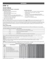
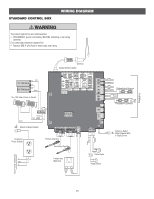
STANDARD CONTROL BOX WIRING DIAGRAM To protect against fire and electrocution: • DISCONNECT power and battery BEFORE installing or servicing LA40o0pWerIRatINoGr. DIAGRAM PLASTIC E-BOX 4EC7FN-o?:?r??c?o??ntinued protection against fire: Re•fereRnecep: l0a6c-3e69O28NLY with fuse of same type and rating. 11/19/13 Antenna Coaxial Antenna Cable Red 12V 7AH Battery 12V 7AH Battery Black Two 12V Solar Panels in Series -+ -+ To J15 Black Blocking Red Diode Attach to Metal Chassis Accessory Power Outlets Primary Operator Secondary Operator Input Power Connection L Transformer GND (Optional) N + - Yellow Black Red White White + + - + - Photoelectric Sensors + - + + + Photoelectric Sensors Attach to Outlet Metal Chassis With a Single Screw Red Black Piezo Alarm Reset Switch Field Wiring Edge Edge 49
-
 1
1 -
2
-
3
-
4
-
5
-
6
-
7
-
8
-
9
-
10
-
11
-
12
-
13
-
14
-
15
-
16
-
17
-
18
-
19
-
20
-
21
-
22
-
23
-
24
-
25
-
26
-
27
-
28
-
29
-
30
-
31
-
32
-
33
-
34
-
35
-
36
-
37
-
38
-
39
-
40
-
41
-
42
-
43
-
 44
44 -
 45
45 -
 46
46 -
 47
47 -
 48
48 -
 49
49 -
 50
50 -
 51
51 -
 52
52 -
 53
53 -
 54
54
 |
 |
