LiftMaster LA500 LA500 Manual
LiftMaster LA500 Manual
 |
View all LiftMaster LA500 manuals
Add to My Manuals
Save this manual to your list of manuals |
LiftMaster LA500 manual content summary:
- LiftMaster LA500 | LA500 Manual - Page 1
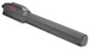
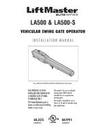
LA500 & LA500-S VEHICULAR SWING GATE OPERATOR INSTALLATION MANUAL Your model may look different than the model illustrated in this manual. THIS PRODUCT IS TO BE INSTALLED AND SERVICED BY A TRAINED GATE SYSTEMS TECHNICIAN ONLY. Visit www.liftmaster.com to locate a professional installing dealer in - LiftMaster LA500 | LA500 Manual - Page 2
- LiftMaster LA500 | LA500 Manual - Page 3
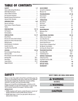
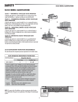
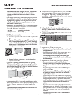
attempting to install, operate or maintain the operator, you must read and fully understand this manual and follow all safety instructions. • DO NOT attempt repair or service of your gate operator unless you are an Authorized Service Technician. 1 SAFETY SYMBOL AND SIGNAL WORD REVIEW MECHANICAL - LiftMaster LA500 | LA500 Manual - Page 4
to service the general public. CLASS IV- RESTRICTED ACCESS VEHICULAR GATE OPERATOR A vehicular gate operator (or GATE OPERATOR ENTRAPMENT PROTECTION UL325 Classification Swing Gate Operator Primary Type Secondary Type CLASS I-CLASS IV A B1 or B2 In order to complete a proper installation - LiftMaster LA500 | LA500 Manual - Page 5
Instructional and Precautionary Signage 4. Install the gate operator only when: a. The operator is appropriate for the construction and the usage class of the gate. b. All openings of a horizontal slide gate edge of a swing gate. Additionally, if the bottom edge of a swing gate is greater than - LiftMaster LA500 | LA500 Manual - Page 6
be disabled when a manually operated gate is retrofitted with a powered gate operator. A gate latch shall not be installed on an automatically operated gate. 3.1.5 All gates shall be designed with sufficient lateral stability to assure that the gate will enter a receiver guide, refer to ASTM F2200 - LiftMaster LA500 | LA500 Manual - Page 7
If a monitored photoelectric sensor is not working or loses power or the beam is blocked, then ALL gate operation in that direction will stop. Unmonitored photoelectric sensor models AOMRON and RETROAB are also acceptable. Safety Non-Contact Sensor Sensor for Close Cycle Sensor for Open Cycle 5 - LiftMaster LA500 | LA500 Manual - Page 8
edges, and post mounted both inside and outside a horizontal swing gate. Non-contact sensors such as photo eyes MUST be mounted across the gate opening and operate during BOTH the open and close cycles. • Entrapment protection devices MUST be installed to protect anyone who may come near a moving - LiftMaster LA500 | LA500 Manual - Page 9
. • SAVE THESE INSTRUCTIONS. • ALWAYS wear protective gloves and eye protection when changing the battery or working around the battery compartment. TROUBLESHOOTING To protect against fire and electrocution: • DISCONNECT power (AC or solar and battery) BEFORE installing or servicing operator. For - LiftMaster LA500 | LA500 Manual - Page 10
Bag 4.21" (10.7 cm) 5.83" (14.8 cm) Operator Model LA500 (1) Model LA500-S (2) 40.35" (102.5 cm) Post Bracket Gate Bracket Warning Signs (2) and Warranty Card OR Key (2) Terminal Block Connector MODEL LA500-S ONLY Standard Control Box with Batteries 12 Vdc 7AH (2) Large Metal Control Box - LiftMaster LA500 | LA500 Manual - Page 11
selectable operation: - OPEN LIMIT: ON at open limit switch - CLOSE LIMIT: OFF at close limit switch - GATE MOVING: ON with gate moving - PRE-ALERT DELAY: ON 3 seconds before gate motion - TAMPER: ON when gate manually pulled from close limit - POWER: ON with AC or Solar power available - LiftMaster LA500 | LA500 Manual - Page 12
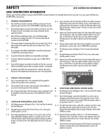
, proper grounding can protect the gate operator in most cases. Check national and local codes for proper depth GATE Gate must be constructed and installed according to ASTM F2200 standards (refer to page 4). Gate must fit specifications of operator (refer to specifications). CONDUIT Conduit - LiftMaster LA500 | LA500 Manual - Page 13
TYPES Identify your installation type. The installation steps in this manual will show a typical Pull-to-Open application. PULL-TO-OPEN Column Install Post Install Gate Hinge Gate Hinge PUSH-TO-OPEN Column Install Gate Hinge SITE PREPARATION Post Install Gate Hinge Heavy Steel Plate - LiftMaster LA500 | LA500 Manual - Page 14
a few pickets, or they could bend. ! DO NOT install upside down. ! DO NOT install on uphill or downhill gates. DO NOT install on ANY pedestrian passageways, doorways, or gates. DO NOT install next to sprinklers or any area that may expose the bottom of operator to water. 12 DO NOT over-bend the - LiftMaster LA500 | LA500 Manual - Page 15
INSTALLATION MANUAL RELEASE + DETERMINE THE POSITION OF THE POST BRACKET MANUAL RELEASE 1 Insert the key into the lock and turn it 180 degrees counterclockwise. 2 Turn the release lever 180 degrees counterclockwise. The operator is now in manual mode. If this operator is a replacement for a - LiftMaster LA500 | LA500 Manual - Page 16
. Tack weld the gate bracket in this position. Gate Hinge Point 27.75" Gate Bracket Location 2.25" WELD THE BRACKETS 1 Position the operator on the brackets and make sure the operator is level and positioned correctly on the gate. 2 Remove the operator from the gate. 3 Completely weld around - LiftMaster LA500 | LA500 Manual - Page 17
the nut a half turn, making sure not to overtighten. Make sure the trolley does not reach the fully open or fully closed position. Post Bracket ATTACH THE OPERATOR TO THE BRACKETS Gate Bracket For dual gate applications, repeat the previous installation steps to install the second operator. 15 - LiftMaster LA500 | LA500 Manual - Page 18
5 feet (1.52 m) of the gate operator. Mount the control box as high as possible for best radio reception. Make sure the control box is level. NOTE: The expansion board DOES NOT need to be removed for a wall or column mount installation. 1 Remove the screws and open the control box. 2 Disconnect the - LiftMaster LA500 | LA500 Manual - Page 19
(1.52 m) of the gate operator. Mount the control box as high as possible for best radio reception. Make sure the control box is level. 1 Open the control box. The control box door may be removed by opening the door 90°. Lift the door from the hinges and set aside until the installation is complete - LiftMaster LA500 | LA500 Manual - Page 20
its integrity, replace it with a single wire length. 1 Install the earth ground rod within 3 feet of the control box. 2 Run wire from the earth ground rod to the control box. NOTE: If the operator is not grounded properly the range of the remote controls will be reduced. 18 To Control Box Check - LiftMaster LA500 | LA500 Manual - Page 21
. 2 Extend the operator cable and wires to the Gate 1 connector and connect as shown. 3 Tighten watertight connector nut. BR GRN WHT YEL BLU RE BR RN WHT YEL BLU RE S LAR / HARGER + - GATE 1 GATE 2 ! If installing one operator, proceed to page 22. If installing two operators, continue to the - LiftMaster LA500 | LA500 Manual - Page 22
items are required to complete the junction box installation: • 4 x 4 Junction Box with 3/4" NPT threaded port holes • Screws • PVC Conduit 1 Trench across driveway to bury the extension cable. Use PVC conduit to prevent damage to cables. 2 Open the junction box by removing screws (4) and set - LiftMaster LA500 | LA500 Manual - Page 23
connector nut to secure extension cable to control box. GATE 1 GATE 2 Extension Cable BRO GRN WHT YEL BLU RED BRO GRN WHT YEL BLU RED SO AR / CHARGER + ! ! SET THE BIPART DELAY Occasionally in dual gate installations, one gate will need to open first and close second. This would happen if - LiftMaster LA500 | LA500 Manual - Page 24
PER DAY Swing Gate Installation (6 ft. 1200 lb. gate/ 19 ft. 500 lb. gate) TOROID POWERED BATTERY POWERED TRANSFORMER POWERED 50 mA 100 mA 300 mA ACCESSORY CURRENT DRAW ✔ ✔ ✔ ✔ ✔ ✔ ✔ ✔ ✔ SINGLE GATE DUAL GATE 7AH 33AH Batteries 7AH 33AH Batteries Batteries (optional for Batteries (optional - LiftMaster LA500 | LA500 Manual - Page 25
CHARGER + - GROUND ID RESET ALARM Red Black (to solar panels) + - + - POWER WIRING + CONNECT BATTERIES NUMBER OF CYCLES PER DAY (SOLAR) Swing Gate Installation (6 ft. 1200 lb. gate/19 ft. 500 lb.) Single Gate CONFIGURATION ZONE 1 (6 Hrs sunlight/day) ZONE 2 (4 Hrs Sunlight/day) ZONE - LiftMaster LA500 | LA500 Manual - Page 26
Control Box (XLM) solar application ONLY. A wall or column mount installation is recommended when using the 33AH batteries. A battery tray (model K10-36183) and battery harness (model K94-36596) are required for 33AH applications. CONNECT BATTERIES + ENGAGE THE OPERATOR Battery Connector J15 Plug - LiftMaster LA500 | LA500 Manual - Page 27
FORCE ADJUSTMENT For dual gate applications the limits will have to be set for each operator. The gate MUST be attached to the operator before setting the limits and force. 1 1 Set the GATE switch to the 1 position. E PRESS & RELEASE 2 TI TO CL 3 TO BEGIN (SECOND SET OPEN SET CLOSE LIMIT - LiftMaster LA500 | LA500 Manual - Page 28
any adjustments are made, test the operator: 1 Open and close the gate with the TEST BUTTONS, ensuring that the gate is stopping at the proper open and close limit positions. 2 Place a solid object between the open gate and a rigid structure. Ensure that the gate, the solid object, and the rigid - LiftMaster LA500 | LA500 Manual - Page 29
STOP DESCRIPTION Program a single button on the remote control for open only. The Timer-to-Close can be set to close the gate. Program one remote control button as an open, close, and stop. PROGRAMMING STEPS 1. Press and release the LEARN button (operator will beep and green XMITTER LED will light - LiftMaster LA500 | LA500 Manual - Page 30
a LiftMaster remote control or SINGLE BUTTON on the control board will close the gate and return the operator to normal operation. When the gate is in the open position, activation of the remote control button will NOTE: If an alternative radio receiver is wired to the operator, the receiver must - LiftMaster LA500 | LA500 Manual - Page 31
Use only LiftMaster part 29-NP712 for replacement batteries. The standard control box comes with two 7AH batteries. Two 33AH (A12330SGLPK) may be used in place of the 7AH batteries for a Large Metal Control Box solar installation. A battery tray (model K10-36183) and battery harness (model K94-36596 - LiftMaster LA500 | LA500 Manual - Page 32
is for programming remote controls and the network. The TIMER-TO-CLOSE (TTC) dial can be set to automatically close the gate after a specified time period. The TTC is factory set to OFF. If the TTC is set to the OFF position, then the gate will remain open until the operator receives another command - LiftMaster LA500 | LA500 Manual - Page 33
off when motor is off. Normally - open (N.O.) output for solenoid locks Relay activates prior to motor activation and during motor run. Relay is off when motor is off. 24 Vdc voltage out to power accessories, will turn off when gate is not in motion to save battery power Always on if Expansion Board - LiftMaster LA500 | LA500 Manual - Page 34
-Close). AC FAIL OPEN/BATT Switch OPEN: Loss of AC power will cause gate to immediately OPEN and remain OPEN until AC power is restored (enabling the Timer-to-Close). BATT: With loss of AC power, gate will remain in present position and operator is powered from batteries. LSOwWitchBATT/EXIT LOOP - LiftMaster LA500 | LA500 Manual - Page 35
Close at OPEN limit. Opens a closing gate and holds open an open gate. Close command - closes an open gate. Soft N Exit Input Barrier Arm Operator C Auxiliary NO Command ON + SW OWER CC SS RY XP B ARD R RN WT E LU R D SO AR / CH RG R GR UND ID ES T LA M Expansion Board Shadow Input - LiftMaster LA500 | LA500 Manual - Page 36
gate is manually tampered with by being pushed off of close limit Use during servicing only to determine operator cycles Typically not required. Normally set to OPEN. If powered from battery and battery is low, gate stays open. Normally set to OFF. Interrupt loop reverses a closing gate. For DUAL - LiftMaster LA500 | LA500 Manual - Page 37
first you will need a 3-button remote control that has been programmed for OPEN, CLOSE, and STOP. Refer to the Programming section. NC NO + ON + W XP INITIAL LIMITS AND FORCE ADJUSTMENT For dual gate applications the limits will have to be set for each operator. The gate MUST be attached to the - LiftMaster LA500 | LA500 Manual - Page 38
potential problems with the operator. NOTE: When cycling or disconnecting power (ac/dc) to the control board, it is recommended that you unplug the J15 and Solar/Charger plug. LIMIT SETUP LEDS GREEN XMITTER LED DIAGNOSTIC CODES LEDS STATUS LEDS OPEN CLOSE STOP SET OPEN SET CLOSE MOVE GATE - LiftMaster LA500 | LA500 Manual - Page 39
timer is cancelled GATE MOVING OFF The gate is stopped ON The gate is opening or closing FASTEST BLINK The operator is in E2 BATT LOW OFF No battery error ON Battery low error SLOW BLINK Battery dead error MEDIUM BLINK Battery over current error FAST BLINK Battery over voltage error - LiftMaster LA500 | LA500 Manual - Page 40
TROUBLESHOOTING TROUBLESHOOTING CHART FAULT Operator does not run and diagnostic LED not on. Control board powers up, but motor does not run. Relay clicks with command, but motor does not turn on. Arm moves, but cannot set correct limits. Gate does not fully open or fully close when setting limits - LiftMaster LA500 | LA500 Manual - Page 41
or repair gate as needed. c) Check all Entrapment Protection Device inputs for an active sensor d) Check all Open and Close inputs for an active input e) Check all vehicle detector inputs for an active detector f) Battery voltage must be 22.0 Vdc or higher. Charge batteries by AC or solar power or - LiftMaster LA500 | LA500 Manual - Page 42
. On dual-gate system, one gate is not commanding the other. On dual-gate system, incorrect gate opens first or closes first. Alarm beeps when running. a) Double entrapment occurred a) Low battery a) Defective or incorrect Operator-to-Operator wiring b) Incorrect Operator-to-Operator wireless - LiftMaster LA500 | LA500 Manual - Page 43
TROUBLESHOOTING TROUBLESHOOTING CHART FAULT Accessories connected to Accessory power not working correctly b) Replace defective control board a) Check that Quick Close setting is ON b) Check operation of Interrupt Loop detector c) Replace defective Expansion board a) Check that Anti-Tail setting - LiftMaster LA500 | LA500 Manual - Page 44
Transformer 200 VA STANDARD CONTROL BOX Field Wiring Wh te White Purple Black Red Antenna OPEN CLOSE STOP SET OPEN SET CLOSE MOVE GATE a Single Screw Primary Operator Secondary Operator Two 12V Solar Panels in Series + power and battery BEFORE installing or servicing operator. For continued - LiftMaster LA500 | LA500 Manual - Page 45
Piezo Alarm N.C. Secondary Operator Two 12V Solar Panels in Series + - + - Reset Switch Wire Loop Wire Loop Wire Loop Field Wiring WIRING DIAGRAMS To protect against fire and electrocution: • DISCONNECT power and battery BEFORE installing or servicing operator. For continued protection - LiftMaster LA500 | LA500 Manual - Page 46
homeowner to operate gate operator from outside by entering a 4-digit code on a specially designed keypad. Model 877MAX MISCELLANEOUS REMOTE ANTENNA EXTENSION KIT The remote antenna extension kit allows the antenna to be remotely installed. Model 86LM WIRELESS ACCESS CONTROL RECEIVER Access control - LiftMaster LA500 | LA500 Manual - Page 47
9 APOW3 10 29-NP712 Transformer Single Battery NOT SHOWN K77-36541 Antenna LARGE METAL CONTROL BOX (XLM) NOT SHOWN K74-34696-3 Large Metal Control Box (XLM) Only K76-34771 K94-36596 Outlet Battery Harness GATE OPERATOR ARM ITEM PART NUMBER DESCRIPTION 11 LA500 Primary Arm 12 KSWG - LiftMaster LA500 | LA500 Manual - Page 48
OF BATTERIES. THIS LIMITED WARRANTY DOES NOT COVER ANY PROBLEMS WITH, OR RELATING TO, THE GATE OR GATE HARDWARE, INCLUDING BUT NOT LIMITED TO THE GATE SPRINGS, GATE ROLLERS, GATE ALIGNMENT OR HINGES. THIS LIMITED WARRANTY ALSO DOES NOT COVER ANY PROBLEMS CAUSED BY INTERFERENCE. ANY SERVICE CALL
-
 1
1 -
 2
2 -
 3
3 -
 4
4 -
 5
5 -
 6
6 -
 7
7 -
8
-
9
-
10
-
11
-
12
-
13
-
14
-
15
-
16
-
17
-
18
-
19
-
20
-
21
-
22
-
23
-
24
-
25
-
26
-
27
-
28
-
29
-
30
-
31
-
32
-
33
-
34
-
35
-
36
-
37
-
38
-
39
-
40
-
41
-
42
-
43
-
44
-
45
-
46
-
47
-
48
 |
 |

LA500 &
LA500-S
VEHICULAR SWING GATE OPERATOR
INSTALLATION MANUAL
UL325
compliant
UL991
compliant
This model is for use on vehicular
passage gates ONLY and not
intended for use on pedestrian
passage gates.
This model is intended for use in
Class I, II, III and IV vehicular swing
gate applications.
THIS PRODUCT IS TO BE
INSTALLED AND SERVICED BY
A TRAINED GATE SYSTEMS
TECHNICIAN ONLY.
Visit www.liftmaster.com to
locate a professional installing
dealer in your area.
Your model may look different than the model illustrated in this manual.