LiftMaster LA500 LA500 Manual - Page 24
Power Wiring, Maximum Wire - la 500 gate operator
 |
View all LiftMaster LA500 manuals
Add to My Manuals
Save this manual to your list of manuals |
Page 24 highlights
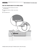
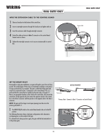
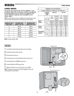
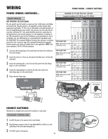
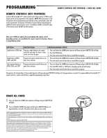
WIRING POWER WIRING This operator can be wired for either 120 Vac (standard) or a solar panel (not provided). Follow the directions according to your application. For dual gate applications, power will have to be connected to each operator. Main power supply and control wiring MUST be run in separate conduits. NOTE: If using an external receiver use shielded wire for the connections or mount the receiver away from the operator to avoid interference with the operator. AMERICAN WIRE GAUGE (AWG) 14 12 10 8 6 4 MAXIMUM WIRE LENGTH (120 VAC) 130 feet 205 feet 325 feet 520 feet 825 feet 1312 feet NOTE: Use copper conductors ONLY. MAXIMUM WIRE LENGTH (240 VAC) 260 feet 410 feet 650 feet 1040 feet 1650 feet 2624 feet POWER WIRING NUMBER OF CYCLES PER DAY Swing Gate Installation (6 ft. 1200 lb. gate/ 19 ft. 500 lb. gate) TOROID POWERED BATTERY POWERED TRANSFORMER POWERED 50 mA 100 mA 300 mA ACCESSORY CURRENT DRAW ✔ ✔ ✔ ✔ ✔ ✔ ✔ ✔ ✔ SINGLE GATE DUAL GATE 7AH 33AH Batteries 7AH 33AH Batteries Batteries (optional for Batteries (optional for (standard) Large Metal (standard) Large Metal Control Box) Control Box) Continuous Continuous Continuous Continuous Continuous Continuous Continuous Continuous Continuous Continuous Continuous Continuous Continuous Continuous Continuous Continuous 215 1202 98 612 207 1292 96 600 200 1249 94 590 178 1111 88 554 1726 1720 1347 1340 1670 1663 1301 1293 1615 1607 1257 1248 1391 1380 1075 1064 120 VAC 1 Turn off the AC power from the main power source circuit breaker. 2 Run the AC power wires to the control box. 3 Remove the junction box cover. 4 Connect the green wire to the earth ground rod wire using a wire nut. 5 Connect the white wire to NEUTRAL using a wire nut. 6 Connect the black wire to HOT using a wire nut. 7 Replace the junction box cover. Ensure the wires are not pinched. NOTE: The operator can also be wired for 240 Vac application. Refer to the Accessory page for more information. STANDARD CONTROL BOX Junction Box Cover LARGE METAL CONTROL BOX (XLM) 22 Junction Box Cover
-
 1
1 -
2
-
3
-
4
-
5
-
6
-
7
-
8
-
9
-
10
-
11
-
12
-
13
-
14
-
15
-
16
-
17
-
18
-
 19
19 -
 20
20 -
 21
21 -
 22
22 -
 23
23 -
 24
24 -
 25
25 -
 26
26 -
 27
27 -
 28
28 -
 29
29 -
30
-
31
-
32
-
33
-
34
-
35
-
36
-
37
-
38
-
39
-
40
-
41
-
42
-
43
-
44
-
45
-
46
-
47
-
48
 |
 |
