LiftMaster MATDCBB3 MEGA ARM / MEGA ARM TOWER Manual - Page 11
Primary/second Wiring
 |
View all LiftMaster MATDCBB3 manuals
Add to My Manuals
Save this manual to your list of manuals |
Page 11 highlights
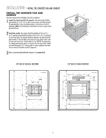
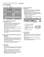
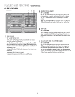
WIRING » PRIMARY/SECOND WIRING PRIMARY/SECOND WIRING In a primary/second configuration, either operator can be the primary. 1 Choose an operator to be the primary and then direct all control wiring to it (also install vehicle detectors and receivers in it). 2 At the primary, any input (at J5) with control wires (detectors, receivers, keypads, timers, etc.) to it must also be run to the same terminals of the second. Along with these control wires, both operators MUST share a common ground connection from chassis to chassis (or from common to common, i.e., primary gate J5 terminal #12 to second gate J5 terminal #12). EXAMPLE: If only open and close are used at primary then three wires will run between gates (Figure 1). 3 If it is required that if one gate senses an obstruction, the other reverses also, then 3 additional wires must be run between the primary J3 and second J3 (Figure 2). These connections are for transmitting IRD (obstruction signals) between both operators. This will allow the primary or second to inform the other that a closing obstruction has occurred and for it to reverse and open. SET switches on S2, 1-8 the same on both gates. FIGURE 1 Primary J5 1 2 3 4 5 6 7 8 9 10 11 12 Close Open Common 1 2 3 4 5 6 7 8 9 10 11 12 Second J5 FIGURE 2 RX GND TX 12 34 Primary J3 Second J3 IRD - Obstruction Signal Connections Terminal 1 of Primary must go to terminal 4 of Second and terminal 1 of Second must go to terminal 4 of Primary. Terminal 2 of Primary must go to terminal 2 of Second. 12 34 RX GND TX 11
-
 1
1 -
2
-
3
-
4
-
5
-
 6
6 -
 7
7 -
 8
8 -
 9
9 -
 10
10 -
 11
11 -
 12
12 -
 13
13 -
 14
14 -
 15
15 -
 16
16 -
17
-
18
-
19
-
20
-
21
-
22
-
23
-
24
 |
 |
