LiftMaster RSL12V RSL12V Wiring Diagram Manual - Page 1
LiftMaster RSL12V Manual
 |
View all LiftMaster RSL12V manuals
Add to My Manuals
Save this manual to your list of manuals |
Page 1 highlights
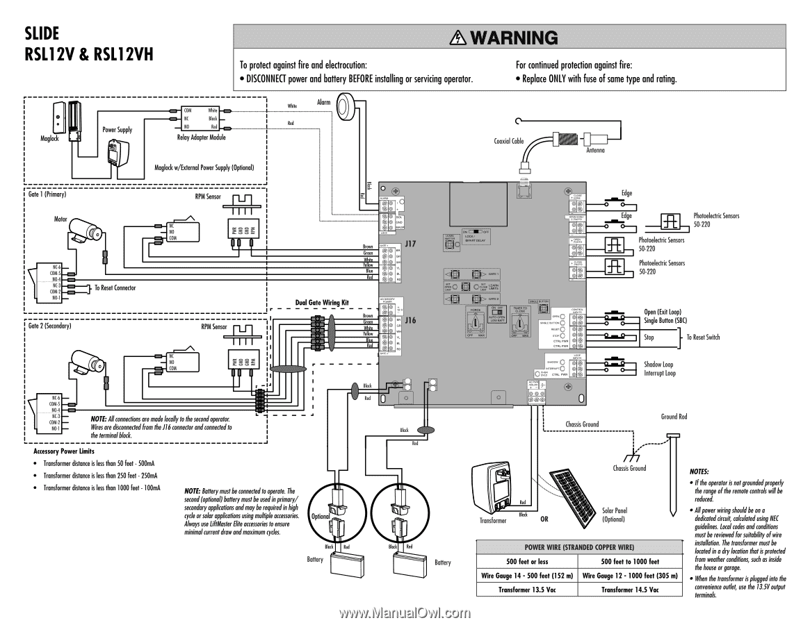
SLIDE RSL12V & RSL12VH ®WARNING To protect against fire and electrocution: • DISCONNECT power and battery BEFORE installing or servicing operator. For continued protection against fire: • Replace ONLY with fuse of same type and rating. • Maglock Power Supply C0M YMile NC Mad( NO Red Relay Adapter Mod le Red J__ Alarm Maglock w/Edernal Power Supply (Optional) Coaxial Cable Antenna Gate 1 (Primary) Motor 0 NC-6 00M-5 NO-4 C0NICA-32 NO-1 - To Reset Connector Gate 2 (Secondary) 0 RPM Sensor IIII NC NO C0M r RPM Sensor III! ' NO €SSE C0M O SOL OND e Brow J17 Green ice BI Red 40 Dual Gate Wiring Kit Brown Gre • • J16 • • 0 • Mock NC-6 - Red C0M-5 - NO-4 NC-3 00M-2 - NOTE. Allconnections are made locally to the secondoperator. NO-1 - Wires ore disconnectedfrom the J16 connector andconnected to the terminalblock. Accessory Power limits • Transformer distance is less than 50 feet - 500mA • Transformer distance is less than 250 feet - 250mA • Transformer distance is less than 1000 feet - 100mA NOTE: Batterymustbe connected to operate. The second(optional)batterymustbe usedinprimary/ secondary applicationsandmay be requiredinhigh cycle orsolar applications usingmultiple accessories. Always use !Master Elite armories to ensure minimalcurrent drawandmaximum cycles. Optional BM ■ Red Battery Mock Red YI Bloc Red a. maw LOCK / SMART DELAY - FORCE ON OFF AUTO OPER LON SKIT MEW • -0 40 • 0 • OD -0 4r.m, Op ONI Edge o1 Edge .11 O-i Photoelectric Sensors 50-220 fE Photoelectric Sensors 50-220 Photoelectric Sensors 50-220 -6 -To A -6 -_ CTRL PWR on - CTRL PWR s Open (Exit Loop) e•m•g-__, Single Button (SBC) g•m•g- I Stop To Reset Switch } =O 74(-6 _ Cr CTRL f ,M, •o O Shadow Loop 1)- 1 Interrupt Loop e 040) 0 Chassis Ground Ground Rod Battery Chassis Ground Red Transformer Block OR Solar Panel (Optional) POWER WIRE (STRANDED COPPER WIRE) 500 feet or less 500 feet to 1000 feet Wire Gauge 14 - 500 feet (152 m) Wire Gauge 12 -1000 feet (305 m) Transformer 13.5 Vac Transformer 14.5 Vac NOTES: • Ifthe operator is not groundedproperly the range ofthe remote controls willbe reduced. • Allpower wiringshouldbe on a dedicatedMyatt, cokulatedusingNEC guidelines. Local codes and conditions must be reviewed for suitability of wire installation. The transformer must be locatedin a drylocation thatisprotected from weather conditions, such as inside the house or garage. • When the transformer ispluggedinto the convenience outlet, use the 13.5V output terminals.
-
 1
1 -
 2
2
 |
 |