LiftMaster SD GSD Manual
LiftMaster SD Manual
 |
View all LiftMaster SD manuals
Add to My Manuals
Save this manual to your list of manuals |
LiftMaster SD manual content summary:
- LiftMaster SD | GSD Manual - Page 1
SLIDE DOOR OPERATOR MODELS SD & GSD ADDENDUM 2 YEAR W A R R A N T Y Serial # (located on electrical box cover) Installation Date Wiring Type NOT FOR RESIDENTIAL USE 41B6 LISTED DOOR OPERATOR - LiftMaster SD | GSD Manual - Page 2
plus 4' - 3" 18" Min. 17.13" 17.46" FIGURE 1 Model GSD Single Slide Door Layout Manual Release *Fusible Link Cylindrical Weight 13.08" 4" Adjustable clearance for door movement between wall and operator. 7.5" Max. 6.0" Min. 13.00" Door Travel plus 4' - 3" 24.00" 24.00" 10.50" 20.53 - LiftMaster SD | GSD Manual - Page 3
due to accidental locking. IMPORTANT This manual supplement includes only mechanical assembly instructions for your slide door operator. For complete list of operator features, specifications and wiring instructions, refer to the Owners Manual supplied with your operator. HARDWARE KITS KIT PART - LiftMaster SD | GSD Manual - Page 4
ASSEMBLY The slide door operator should be pre-assembled as follows before installation: unit and reinstall the spacer within the rails, tightening the bolts securely. For a right to open single-sliding door, the powerhead should be mounted on the right hand end of the track with the pulleys - LiftMaster SD | GSD Manual - Page 5
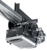
MOUNTING ASSEMBLY IDLER SHAFT ASSEMBLY ANGLE MOUNTING BRACKET FIGURE 4 HEX HEAD BOLT, 3/8-16 x 1" LONG (2 PER BRACKET) TRACK SPACER FLATWASHER, 1/8" (2 PER BRACKET) BI-PART SLIDER CARRIAGE (SEE FIGURE 2) SLIDER CARRIAGE (SEE FIGURE 1) POWERHEAD SERRATED FLANGE HEX NUT, #10 BI-PART SLIDER - LiftMaster SD | GSD Manual - Page 6
or 18" to the right of this line if the door slides right to close (see figure 1). NOTE: For bi-parting doors, omit this step. The track should extend 3-1/2 feet beyond the door opening (see figure 2). 3. Set the assembled operator into position and mark the holes for the angle mounting brackets - LiftMaster SD | GSD Manual - Page 7
of door (6 to 12 inches below top of door) so that the fusible link will be in door opening when door is open (see OPERATING INSTRUCTIONS POWER AND CONTROL WIRING: Refer to the Owners Manual supplied with your operator for all power and control wiring. ELECTRICAL OPERATION: The door can be operated - LiftMaster SD | GSD Manual - Page 8
01-10589D c 1998, The Chamberlain Group, Inc. All rights Reserved
-
 1
1 -
 2
2 -
 3
3 -
 4
4 -
 5
5 -
 6
6 -
 7
7 -
8
 |
 |

SLIDE DOOR OPERATOR
MODELS SD & GSD
ADDENDUM
NOT FOR RESIDENTIAL USE
LISTED
DOOR
OPERATOR
41B6
Serial #
(located on electrical box cover)
Installation Date
Wiring Type
2
YEAR
WARRANTY