LiftMaster SD GSD Manual - Page 3
Preparation, Hardware Kits - operator
 |
View all LiftMaster SD manuals
Add to My Manuals
Save this manual to your list of manuals |
Page 3 highlights
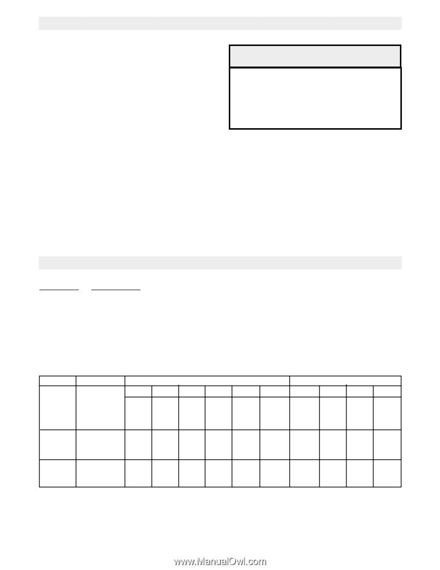
PREPARATION 1. Unpack carton, checking for possible damage during shipping. Damage claims must be filed with the freight carrier. Check that the nameplate data accurately specifies the operator that was ordered. Verify that the following parts listed below are included in the carton. 2. Check to make sure that the available power supply to be connected to the operator is of the same voltage, phase, frequency, and wattage as indicated on the nameplate of the operator. 3. In order for the door operator to function correctly, it is important that the door be properly aligned and working smoothly. Make any necessary corrections to the door to assure this before beginning operator installation. In addition, disconnect and remove all locking devices from the door to prevent damage or personal injury due to accidental locking. IMPORTANT This manual supplement includes only mechanical assembly instructions for your slide door operator. For complete list of operator features, specifications and wiring instructions, refer to the Owners Manual supplied with your operator. HARDWARE KITS KIT PART # *K77-10473 *K77-10474 K75-10470 K75-10471 K75-10469 K75-16339 DESCRIPTION Complete Hardware Kit for Single Slide door Complete Hardware Kit for Bi-Sliding doors Trolley Slider Kit for Single Slide door Trolley Slider Kit for Bi-Sliding doors Door Disconnect Kit Wall Bracket Kit PART # DESCRIPTION SINGLE SLIDE OPENING WIDTH BI-PART SLIDE OPENING WIDTH To 8' 10' 12' 14' 16'-20' 22'-24' To 8' 8'-12' 12'-16' 16'-20' See chart Track 10-5808 10-5810 10-5812 10-5814 10-5820 10-5824 10-5812 10-5814 10-5820 10-5824 See chart Roller Chain 19-5114 19-5114 19-5114 19-5114 19-5120 19-5124 19-5114 19-5116 19-5118 19-5120 K75-16339 Wall brackets 4 4 4 4 5 6 4 5 6 6 * (4) wall brackets are included in the standard hardware kit. Single doors over 14' or Bi-Part doors over 8' will require additional wall brackets, refer to chart. 3
-
 1
1 -
 2
2 -
 3
3 -
 4
4 -
 5
5 -
 6
6 -
 7
7 -
 8
8
 |
 |