Linksys SPA-841 Cisco WBP54G Wireless-G Bridge for Phone Adapters User Guide - Page 15
Power on the Bridge Screen, Router Screen
 |
View all Linksys SPA-841 manuals
Add to My Manuals
Save this manual to your list of manuals |
Page 15 highlights
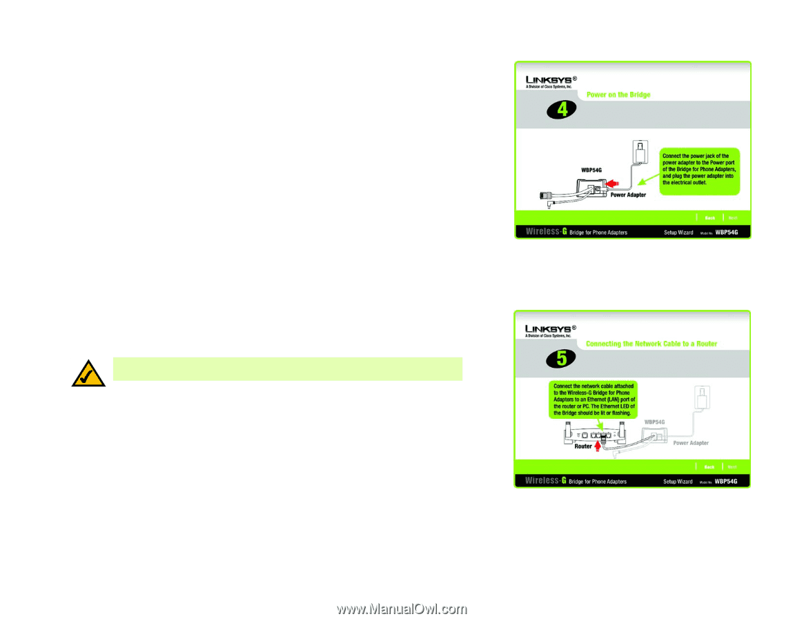
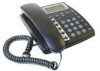
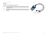
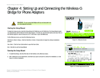
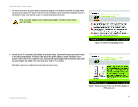
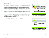
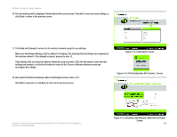
Wireless-G Bridge for Phone Adapters 5. Connect the power jack to the Power port of the Bridge. Then plug the power adapter into an electrical outlet. Click Next to proceed with the installation process, or click Back to return to the previous screen. 6. You will use the combination Ethernet network and power cable attached to the Bridge. Connect the Ethernet network cable of the Bridge to an Ethernet network (LAN) port of the router or PC. (Do not use the power cable now; you will use it later.) NOTE: If you connect the Bridge to a router, make sure the Bridge and PC running the Setup Wizard are connected to the Ethernet network (LAN) ports of the same router. Make sure the Bridge's Ethernet LED is solidly lit or flashing. Click Next to proceed, or click Back to return to the previous screen. Figure 4-5: Power on the Bridge Screen Chapter 4: Setting Up and Connecting the Wireless-G Bridge for Phone Adapters Running the Setup Wizard Figure 4-6: Connecting the Network Cable to a Router Screen 9
-
 1
1 -
2
-
3
-
4
-
5
-
6
-
7
-
8
-
9
-
 10
10 -
 11
11 -
 12
12 -
 13
13 -
 14
14 -
 15
15 -
 16
16 -
 17
17 -
 18
18 -
 19
19 -
 20
20 -
21
-
22
-
23
-
24
-
25
-
26
-
27
-
28
-
29
-
30
-
31
-
32
-
33
-
34
-
35
-
36
-
37
-
38
-
39
-
40
-
41
-
42
-
43
-
44
-
45
-
46
-
47
-
48
-
49
-
50
-
51
-
52
 |
 |