Linksys SR2024 Cisco SR2024 24-Port 10/100/1000 Gigabit Switch Quick Start Gui - Page 16
Hardware Installation - 24 port gigabit switch
 |
UPC - 745883557059
View all Linksys SR2024 manuals
Add to My Manuals
Save this manual to your list of manuals |
Page 16 highlights
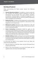
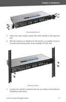
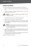
Chapter 3: Installation Hardware Installation To connect network devices to the Switch, follow these instructions: 1. Make sure all the devices you will connect to the Switch are powered off. 2. Connect a Category 5 Ethernet network cable to one of the numbered ports on the Switch. NOTE: Use Category 5e Ethernet network cables for your Gigabit connections. 3. Connect the other end to a PC or other network device. 4. Repeat steps 2 and 3 to connect additional devices. 5. If you are using a miniGBIC port, then connect a miniGBIC module to the miniGBIC port. For detailed instructions, refer to the module's documentation. NOTE: The miniGBIC ports are shared. Do not use port 12 if you are using the miniGBIC1 port. Do not use port 24 if you are using the miniGBIC2 port. 6. Connect the supplied power cord to the Switch's power port, and plug the other end into an electrical outlet. When connecting power, always use a surge protector. 7. Power on the devices connected to the Switch. Each active port's corresponding LED will light up on the Switch. Hardware installation is complete. 10 24-Port 10/100/100 Gigabit Switch
-
 1
1 -
2
-
3
-
4
-
5
-
6
-
7
-
8
-
9
-
10
-
 11
11 -
 12
12 -
 13
13 -
 14
14 -
 15
15 -
 16
16 -
 17
17 -
 18
18 -
 19
19 -
 20
20 -
 21
21 -
22
-
23
-
24
-
25
-
26
-
27
-
28
-
29
-
30
-
31
-
32
-
33
-
34
-
35
-
36
 |
 |