Lowrance Auto-Standby button Metal H1000 Compass Installation Manual
Lowrance Auto-Standby button Metal Manual
 |
View all Lowrance Auto-Standby button Metal manuals
Add to My Manuals
Save this manual to your list of manuals |
Lowrance Auto-Standby button Metal manual content summary:
- Lowrance Auto-Standby button Metal | H1000 Compass Installation Manual - Page 1
compass installation IS- 2506 - Lowrance Auto-Standby button Metal | H1000 Compass Installation Manual - Page 2
Brookes & Gatehouse Ltd Premier Way, Abbey Park, Romsey, SO51 9AQ UK Tel: (+44) (0)1794 518448 Fax: (+44) (0)1794 518077 Global Website: www.BandG.com © 2001 Brookes & Gatehouse Ltd B&G USA 13191 56th Court, Suite 106, Clearwater, Florida 33760 USA Tel: (+1) 727 540 0229 Fax: (+1) 727 540 0281 - Lowrance Auto-Standby button Metal | H1000 Compass Installation Manual - Page 3
and, if not installed and used in accordance with the instructions, may cause harmful interference to radio communications. However, there other qualified technician for additional help if these remedies do not correct the problem. This device meets requirements for CFR47 Part 15 of the FCC limits - Lowrance Auto-Standby button Metal | H1000 Compass Installation Manual - Page 4
émet et utilise une fréquence qui peut rayonner de l'énergie et, si son installation et son utilisation ne sont pas conformes aux instructions, il peut être la cause de parasites nuisibles aux communications radio. Il n'y a cependant aucune garantie que des parasites ne se produiront pas dans - Lowrance Auto-Standby button Metal | H1000 Compass Installation Manual - Page 5
trademark All rights reserved. No part of this manual may be reproduced or transmitted in any form or by any means including photocopying and recording, without the express written permission of B&G. Information in this - Lowrance Auto-Standby button Metal | H1000 Compass Installation Manual - Page 6
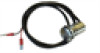
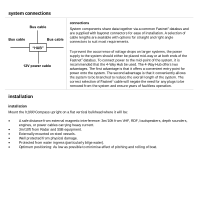
system connections Bus cable Bus cable Bus cable "HUB" 12V power cable connections System components share data together via a common Fastnet2 databus and are supplied with bayonet connectors for ease of installation. A selection of cable lengths are available with options for straight and - Lowrance Auto-Standby button Metal | H1000 Compass Installation Manual - Page 7
electrical connections external connections Two FastNet² connectors are provided at the base of the unit. These connectors allow connection to the rest of the system for the supply of power and data. The table below shows pin functions. 2 3 5 1 4 Front view of male connector pins Pin Number - Lowrance Auto-Standby button Metal | H1000 Compass Installation Manual - Page 8
compass calibration compass calibration Compass calibration sets sensor offset, damping, and allows a compass swing to correct for magnetic deviation. If the compass has not been swung the compass cal menu will show swing required. When this item is selected the display will switch to the start menu - Lowrance Auto-Standby button Metal | H1000 Compass Installation Manual - Page 9
tactical compass function When a compass and a wind sensor are connected to the system, the Tactical Compass function becomes available as a full page display option. After a tack or gybe, and the yacht is sailing a steady course, press the ENTER key to store the displayed heading. Note, to access - Lowrance Auto-Standby button Metal | H1000 Compass Installation Manual - Page 10
compass unit deutsch - Lowrance Auto-Standby button Metal | H1000 Compass Installation Manual - Page 11
warenzeichen Alle Rechte vorbehalten. Ohne die ausdrückliche schriftliche Genehmigung durch B&G dürfen diese Anleitung oder Teile daraus nicht in irgendeiner Form oder mit irgendwelchen Mitteln einschließlich Fotokopie und Aufzeichnung reproduziert oder übertragen werden. Änderungen der - Lowrance Auto-Standby button Metal | H1000 Compass Installation Manual - Page 12
systemverbindungen Bus-kabel Bus-kabel "Verteiler" Bus-kabel verbindungen Systemgeräte nutzen Daten gemeinsam über einen gemeinsamen Fastnet2 Datenbus und verfügen über Bajonett-Steckverbinder für einfache Installation. Verschiedene Kabellängen stehen zur Auswahl mit geraden und Winkel- - Lowrance Auto-Standby button Metal | H1000 Compass Installation Manual - Page 13
elektrische anschlüsse externe anschlüsse An der Gerätebasis befinden sich zwei FastNet² Anschlüsse. Über diese Anschlüsse wird die Verbindung zum System für die Zuführung von Spannung und Daten hergestellt. Die nachstehende Tabelle beschreibt die Stiftbelegung. 2 3 5 1 4 Stift-Nr. 1 2 3 4 5 - Lowrance Auto-Standby button Metal | H1000 Compass Installation Manual - Page 14
kompass-kalibrierung kompass-kalibrierung Die Kalibrierung des Kompasses ermöglicht die Einstellung von Sensorversatz und Dämpfung sowie die Durchführung einer Deviationsbestimmung. Wenn noch keine Deviationsbestimmung durchgeführt wurde, wird im Menü compass cal (Kompass-Kalibrierung) die Angabe - Lowrance Auto-Standby button Metal | H1000 Compass Installation Manual - Page 15
kompass-kalibrierung Nach Beendigung des Vollkreises berechnet der Kompass die Deviationskorrektur, anschließend erscheint passed (erfolgreich durchgeführt) oder failed (fehlgeschlagen) im Display. Nach einer erfolgreichen Deviationsbestimmung wird swing done (Deviationsbestimmung durchgeführt) - Lowrance Auto-Standby button Metal | H1000 Compass Installation Manual - Page 16
speichern eines kurses vom kompass-bildschirm Durch Drücken der Taste ENTER, während die Seite „taktischer Kompass" angezeigt wird, werden der anliegende Kurs automatisch gespeichert und die Funktion „Head-/-Lift-Trend" zurückgesetzt. In diesem Fall wird für zwei Sekunden „Course stored" (Kurs - Lowrance Auto-Standby button Metal | H1000 Compass Installation Manual - Page 17
compass unit español - Lowrance Auto-Standby button Metal | H1000 Compass Installation Manual - Page 18
marca registrada Reservados todos los derechos. Ninguna parte de este manual puede reproducirse ni transmitirse de ninguna forma o por cualquier medio, fotocopia y grabación inclusive, sin el permiso expreso por escrito de B&G. La información de este documento - Lowrance Auto-Standby button Metal | H1000 Compass Installation Manual - Page 19
conexiones del sistema Cable bus Cable bus Cable bus "HUB" conexiones Los componentes del sistema comparten datos a través de un bus de datos Fastnet2 común y se suministran con conectores de bayoneta que facilitan la instalación. Hay disponible una serie de longitudes de cable con opciones - Lowrance Auto-Standby button Metal | H1000 Compass Installation Manual - Page 20
instalación instalación Monte el h1000 Compass de pie en un mamparo vertical plano, donde esté: • A una distancia segura de interferencias magnéticas externas: 3 m de VHF, RDF, altavoces, sondeadores • de profundidad, motores o cables eléctricos de corriente fuerte. • A 3 m de radar y - Lowrance Auto-Standby button Metal | H1000 Compass Installation Manual - Page 21
memoria de la brújula brújula La memoria de la brújula guarda el rumbo en curso y también puede ser definida por el usuario. Se retienen los rumbos de BABOR y ESTRIBOR que se actualizan a cada pulsación de la tecla enter en la página de Tactical Compass (brújula táctical. Cuando se selecciona OK, el - Lowrance Auto-Standby button Metal | H1000 Compass Installation Manual - Page 22
calibración de la brújula calibración de la brújula La calibración de la brújula establece la compensación del sensor y el amortiguamiento y permite que un giro de brújula se corrija para tener en cuenta la desviación magnética. Si la brújula no ha llegado, el menú compass cal (calibración de la br - Lowrance Auto-Standby button Metal | H1000 Compass Installation Manual - Page 23
función de la brújula La función Tactical Compass (brújula táctica) se accede solamente desde la página Compass Composite con una simple pulsación de la tecla ENTER. Después de que un yate ha completado una bordada y ha establecido un rumbo continuo, con la dirección del viento y el rumbo de la brú - Lowrance Auto-Standby button Metal | H1000 Compass Installation Manual - Page 24
ultima información de bordada Cuando se realiza una bordada, el campo Head / Lift de la parte inferior izquierda o derecha de la pantalla es sustituido con el último rumbo para esa bordada. Es decir, el último rumbo que se almacenó pulsando la tecla ENTER. Se muestra una pantalla de muestra para - Lowrance Auto-Standby button Metal | H1000 Compass Installation Manual - Page 25
compass unit français - Lowrance Auto-Standby button Metal | H1000 Compass Installation Manual - Page 26
: 110mm x 95mm x 75mm 12V cc nominale (10 à 16v)) via FastNet2 0,1W nominale -10 à +55ºC -25 à +70ºC Jusqu'à 95% RH IP66 (avec couvercle anti-poussières) Support de fixation - Lowrance Auto-Standby button Metal | H1000 Compass Installation Manual - Page 27
connexions du système Câble Bus Câble Bus "SERVEUR" Câble Bus connexions Les données sont mises en commun pour les composants du système par un bus de données Fastnet2. L'installation des composants est facilitée par les connexions à baïonnette Les câbles sont disponibles en longueurs variées - Lowrance Auto-Standby button Metal | H1000 Compass Installation Manual - Page 28
connexions électriques connexions externes Deux connecteurs FastNet² sont présents au dos de l'unité. Ils permettent le branchement du reste du système pour l'alimentation et le transfert des données. Le tableau ci-dessous indique les fonctions des broches. 2 3 5 1 4 Numéro de broche Signal - Lowrance Auto-Standby button Metal | H1000 Compass Installation Manual - Page 29
calibrage du compas calibrage du compas Le calibrage du compas détermine le décalage axial du capteur, règle la temporisation et permet d'appliquer la déviation magnétique. Si la courbe de déviation du compas n'a pas été établie le menu compas cal indiquera swing required. En sélectionnant swing - Lowrance Auto-Standby button Metal | H1000 Compass Installation Manual - Page 30
fonctions du compas On accède à la fonction Compas tactique uniquement à partir de la page Compas Composite en appuyant une fois sur la touche ENTER. Après un virement de bord ou empannage, lorsque le cap suivi est stable, la direction du vent et le cap compas constants, les voiles étant réglées - Lowrance Auto-Standby button Metal | H1000 Compass Installation Manual - Page 31
compass unit italiano - Lowrance Auto-Standby button Metal | H1000 Compass Installation Manual - Page 32
. Non è permesso riprodurre o trasmettere in qualsiasi forma o con qualsiasi mezzo, compresa fotocopiatura e registrazione, qualsiasi parte di questo manuale senza l'esplicito permesso scritto di B&G. Le informazioni contenute in questo documento sono soggette a modifica senza avviso. B&G si riserva - Lowrance Auto-Standby button Metal | H1000 Compass Installation Manual - Page 33
collegamenti dell'impianto Cavo bus Cavo bus Cavo bus "HUB" collegamenti I componenti dell'impianto condividono i dati tramite un normale bus dati Fastnet2 e sono forniti con connettori a baionetta che ne facilitano l'installazione. I cavi sono disponibili in tutta una serie di lunghezze con - Lowrance Auto-Standby button Metal | H1000 Compass Installation Manual - Page 34
collegamenti elettrici 2 3 5 1 4 collegamenti esterni Alla base dell'unità vi sono due connettori FastNet². Questi connettori permettono il collegamento con il resto dell'impianto per l'alimentazione dell'elettricità e il trasferimento dei dati. La tabella qui sotto indica le funzioni dei pin. - Lowrance Auto-Standby button Metal | H1000 Compass Installation Manual - Page 35
calibratura della bussola La calibratura della bussola imposta lo spiazzamento e lo smorzamento del sensore e permette il giro di bussola per ovviare alle deviazioni magnetiche. Se non è stato eseguito il giro di bussola, il menu compass cal (calibratura bussola) indica che è necessario eseguirlo ( - Lowrance Auto-Standby button Metal | H1000 Compass Installation Manual - Page 36
funzione della bussola La funzione Bussola tattica è accessibile solo dalla pagina Bussola composita premendo un'unica volta il tasto ENTER (Invio). il tasto ENTER (Invio) sul display deve essere premuto dopo che lo yacht ha completato un bordeggio o una strambata e ha stabilito una rotta stabile e - Lowrance Auto-Standby button Metal | H1000 Compass Installation Manual - Page 37
informazioni sull'ultima virata di prora Quando si verifica una virata di prora, il campo Head / Lift nell'angolo inferiore sinistro o destro del display viene sostituito dall'ultima direzione della virata. Vale a dire l'ultima rotta memorizzata premendo il tasto ENTER (Invia). Si riporta di seguito
-
 1
1 -
 2
2 -
 3
3 -
 4
4 -
 5
5 -
 6
6 -
 7
7 -
8
-
9
-
10
-
11
-
12
-
13
-
14
-
15
-
16
-
17
-
18
-
19
-
20
-
21
-
22
-
23
-
24
-
25
-
26
-
27
-
28
-
29
-
30
-
31
-
32
-
33
-
34
-
35
-
36
-
37
 |
 |

compass installation
IS- 2506