MSI 651M-V User Guide
MSI 651M-V - Motherboard - Micro ATX Manual
 |
UPC - 816909005455
View all MSI 651M-V manuals
Add to My Manuals
Save this manual to your list of manuals |
MSI 651M-V manual content summary:
- MSI 651M-V | User Guide - Page 1
651M-V MS-7005 (v2.X) ATX Mainboard G52-M7005X7 i - MSI 651M-V | User Guide - Page 2
radio frequency energy and, if not installed and used in accordance with the instruction manual, may cause harmful interference to radio communications. Operation of this equipment in a emission limits. VOIR LA NOTICE D'INSTALLATION AVANT DE RACCORDER AU RESEAU. Micro-Star International MS-7005 ii - MSI 651M-V | User Guide - Page 3
is the intellectual property of MICRO-STAR INTERNATIONAL. We take every care is a registered trademark of Microsoft Corporation. Windows® 98/2000/NT/ XP are registered trademarks the Personal Computer Memory Card International Association. Revision History Revision V1.0 V2.0 Revision History First - MSI 651M-V | User Guide - Page 4
. h Visit the MSI homepage & FAQ site for technical guide, BIOS updates, driver updates, and other information: http://www.msi.com.tw & http://www.msi.com. tw/program/service/faq/faq/esc_faq_list.php h Contact our technical staff at: [email protected] Safety Instructions 1. Always read the - MSI 651M-V | User Guide - Page 5
Instructions ...iv Technical Support ...iv Chapter 1. Getting Started 1-1 Mainboard Specifications 1-2 Mainboard Layout 1-4 Chapter 2. Hardware Setup 2-1 Quick Components Guide 2-2 Central Processing Unit: CPU 2-3 Example of CPU 2-11 VGA Connector 2-11 RJ-45 LAN Jack 2-12 Audio Port - MSI 651M-V | User Guide - Page 6
Front Panel Audio Connector: JAUD1 2-16 Chassis Intrusion Switch Connector: JCI1 2-17 Front Panel Connectors: Interrupt Request Routing 2-20 Chapter 3. BIOS Setup 3-1 Entering Setup ...3-2 The Main Menu 3-3 Standard CMOS Features 3-5 Advanced BIOS Features 3-7 Advanced Chipset Features 3-10 - MSI 651M-V | User Guide - Page 7
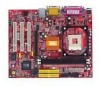
Getting Started Getting Started Thank you for purchasing 651M-V Series (MS-7005) v2.X Micro ATX mainboard. The 651M-V Series is based on SiS® 651 (702 pin BGA) & SiS® 962L MuTIOL Media I/O (371 BGA) chipsets and provides 6 USB 2.0 ports for high-speed data transmission. With - MSI 651M-V | User Guide - Page 8
MS-7005 Micro ATX Mainboard Mainboard Specifications CPU h Socket 478 for P4 processors (Northwood/Prescott) at 400 MHz/533 MHz h Supports up to 3.06GHz. h Hyper-Threading CPU. (For the latest information about CPU, please visit http://www.msi.com.tw/program/ products/mainboard/mbd/ - MSI 651M-V | User Guide - Page 9
. BIOS h 4MB Award BIOS with PNP BIOS, ACPI, SMBIOS 2.3, Green and Boot Block. h Provides DMI 2.0, WFM 2.0, WOL, WOR, chassis intrusion, and SMBus for system management. Dimension h Micro-ATX Form Factor: 24.5 cm (L) x 20.0 cm (W). Mounting h 6 mounting holes. Others h Live BIOS/Live Driver Update - MSI 651M-V | User Guide - Page 10
2 S Y S FA N 1 IDE 2 IDE 1 MS-7005 Micro ATX Mainboard Mainboard Layout Top : mouse Bottom: keyboard CPUFAN1 Top : Parallel Port Bottom: COM A VGA Port Top : Game port Bottom: Line-Out Line-In BAT 1 JCI1 JFP1 JUSB1 Winbond W83697HF BIOS 651M-V Series (MS-7005) v2.X Micro ATX Mainboard 1-4 - MSI 651M-V | User Guide - Page 11
Chapter 2. Hardware Setup Hardware Setup This chapter tells you how to install the CPU, memory modules, and expansion cards, as well as how to setup the jumpers on the mainboard. It also provides the instructions on connecting the peripheral devices, such as the mouse, keyboard, etc. While doing - MSI 651M-V | User Guide - Page 12
MS-7005 Micro ATX Mainboard Quick Components Guide ATX12V, p.2-9 CPU, p.2-3 Back Panel I/O, p.2-10 DDR DIMMs, p.2-7 CPUFAN1, p.2-14 CONN1, p.2-9 FDD1, p.2-14 SYSFAN1, p.2-14 AGP Slot, p.2-20 JSP1, p.2-18 JCD1, p.2-16 PCI Slots, p.2-20 JAUD1, p.2-16 IDE1, - MSI 651M-V | User Guide - Page 13
http://www.msi.com.tw/ program/products/mainboard/mbd/pro_mbd_cpu_support.php Example of CPU Core Speed Derivation Procedure If then CPU Clock Core/Bus ratio CPU core speed = 133MHz = 23 = Host Clock x Core/Bus ratio = 133MHz x 23 = 3.06 GHz Memory Speed/CPU FSB Support Matrix Memory - MSI 651M-V | User Guide - Page 14
MS-7005 Micro ATX Mainboard CPU Installation Procedures for Socket 478 1. Please turn off the power and unplug the power cord before installing the CPU. Open Lever 2. Pull the lever sideways away from the socket. Make sure to raise the lever up to a 90-degree angle. Sliding Plate 90 degree 3. - MSI 651M-V | User Guide - Page 15
important. To dissipate heat, you need to attach the CPU cooling fan and heatsink on top of the CPU. Follow the instructions below to install the Heatsink/Fan: 1. Locate the CPU and its retention mechanism on the motherboard. retention mechanism 2. Position the heatsink onto the retention - MSI 651M-V | User Guide - Page 16
MS-7005 Micro ATX Mainboard 5. Connect the fan power cable from the mounted fan to the 3-pin fan power connector on the board. fan power cable NOTES 2-6 - MSI 651M-V | User Guide - Page 17
size up to 2GB. To operate properly, at least one DIMM module must be installed. For the uplated supporting memory modules, please visit http://www.msi. com.tw/program/products/mainboard/mbd/pro_mbd_trp_list.php. DDR DIMM Slots (DDR 1~2) Introduction to DDR SDRAM DDR (Double Data Rate) SDRAM is - MSI 651M-V | User Guide - Page 18
MS-7005 Micro ATX Mainboard 1) DDR 2 (Bank 2 & 3) Memory Module S/D S/D Maximum System Memory Supported Total Memory 64MB~1GB 64MB~1GB 64MB~2GB S: Single Side D: Double Side will automatically close. Volt Notch MSI Reminds You... You can barely see the golden finger if the module - MSI 651M-V | User Guide - Page 19
Hardware Setup Power Supply The mainboard supports ATX power supply for the power system. into the connector. ATX 12V Power Connector: ATX12V This 12V power connector is used to provide power to the CPU. 11 1 20 10 CONN1 CONN1 Pin Definition PIN SIGNAL PIN SIGNAL 1 3.3V 2 3.3V 3 GND - MSI 651M-V | User Guide - Page 20
MS-7005 Micro ATX Mainboard Back Panel The back panel provides the following connectors: Mouse Parallel Midi/Joystick LAN Keyboard COMA VGA Port L-out L-in MIC USB Ports Mouse Connector The mainboard provides a standard PS/2® mouse mini DIN connector for attaching a PS/2® mouse. You can - MSI 651M-V | User Guide - Page 21
0 Positive Data Channel 0 Ground +5V Negative Data Channel 1 Positive Data Channel 1 Ground VGA Connector The mainboard provides a DB 15-pin female connector to connect a VGA monitor. 5 1 15 11 VGA Connector (DB 15-pin) Pin Signal Description Pin 1 RED 2 3 BLUE 4 5 GND 6 7 GND - MSI 651M-V | User Guide - Page 22
MS-7005 Micro ATX Mainboard RJ-45 LAN Jack The mainboard provides one standard RJ-45 jack for connection to Local Area Network (LAN). You can connect a network cable to the LAN jack. RJ-45 LAN - MSI 651M-V | User Guide - Page 23
can connect a joystick or game pad to this connector. Parallel Port Connector: LPT1 The mainboard provides a 25-pin female centronic connector as LPT. A parallel port is a standard printer port that supports Enhanced Parallel Port (EPP) and Extended Capabilities Parallel Port (ECP) mode. 13 1 25 - MSI 651M-V | User Guide - Page 24
MS-7005 Micro ATX Mainboard Connectors The mainboard provides connectors to connect to FDD, IDE HDD, case, LAN, USB Ports and CPU/System/Power Supply FAN. Floppy Disk Drive Connector: FDD1 The mainboard provides a standard floppy disk drive connector that supports 360K, 720K, 1.2M, 1.44M and 2.88M - MSI 651M-V | User Guide - Page 25
Hardware Setup Hard Disk Connectors: IDE1 & IDE2 The mainboard has a 32-bit Enhanced PCI IDE and Ultra jumper accordingly. IDE2 (Secondary IDE Connector) IDE2 can also connect a Master and a Slave drive. MSI Reminds You... If you install two hard disks on cable, you must configure the second drive to - MSI 651M-V | User Guide - Page 26
MS-7005 Micro ATX Mainboard CD-In Connector: JCD1 The connector is for CD-ROM audio connector. L GND R JCD1 Front Panel Audio Connector: JAUD1 The JAUD1 front panel audio connector allows you to connect to the front panel audio and is compliant with Intel® Front Panel I/O Connectivity Design Guide. - MSI 651M-V | User Guide - Page 27
enter the BIOS setting and clear the status. JCI1 Front Panel Connectors: JFP1 & JFP2 The mainboard provides two front panel connectors for electrical connection to the front panel switches and LEDs. JFP1 is compliant with Intel® Front Panel I/O Connectivity Design Guide - MSI 651M-V | User Guide - Page 28
MS-7005 Micro ATX Mainboard Front USB Connectors: JUSB1/JUSB2 The mainboard provides two USB 2.0 pin headers JUSB1 & JUSB2 that are compliant with Intel® I/O Connectivity Design Guide. USB 2.0 technology increases data transfer rate up to a maximum throughput of 480Mbps, which is 40 times faster - MSI 651M-V | User Guide - Page 29
computer's function. This section will explain how to change your motherboard's function through the use of jumpers. Clear CMOS Jumper: JBAT1 Jumper ) to clear data. Follow the instructions below to clear the data: 1 JBAT1 1 1 3 Keep Data 3 Clear Data MSI Reminds You... You can clear CMOS by - MSI 651M-V | User Guide - Page 30
MS-7005 Micro ATX Mainboard Slots The motherboard provides one AGP slot and five 32-bit PCI bus slots. AGP (Accelerated Graphics Port) Slot The AGP slot allows you to insert the AGP graphics card access main memory. The slot supports 4x/2x AGP card. AGP Slot PCI (Peripheral Component - MSI 651M-V | User Guide - Page 31
you to run SETUP. ” You want to change the default settings for customized features. MSI Reminds You... 1. The items under each BIOS category described in this chapter are under continuous update for better system performance. Therefore, the description may be slightly different from the latest - MSI 651M-V | User Guide - Page 32
MS-7005 Micro ATX Mainboard Entering Setup Power on the computer and the system will start POST -menu. If you want to return to the main menu, just press . General Help The BIOS setup program provides a General Help screen. You can call up this screen from any menu by simply pressing - MSI 651M-V | User Guide - Page 33
this menu for basic system configurations, such as time, date etc. Advanced BIOS Features Use this menu to setup the items of Award® special enhanced features power management. PNP/PCI Configurations This entry appears if your system supports PnP/PCI. PC Health Status This entry shows your PC health - MSI 651M-V | User Guide - Page 34
MS-7005 Micro ATX Mainboard Load Optimized Defaults Use this menu to load factory default settings into the BIOS for stable system performance operations. Set Supervisor Password Use this menu to set Supervisor Password. Set User Password Use this menu to set User Password. - MSI 651M-V | User Guide - Page 35
day month date year Day of the week, from Sun to Sat, determined by BIOS. Readonly. The month from Jan. through Dec. The date from 1 to 31 second>. IDE Primary/Secondary Master/Slave Press PgUp/ or PgDn/ to select [Manual], [None] or [Auto] type. Note that the specifications of your drive - MSI 651M-V | User Guide - Page 36
MS-7005 Micro ATX Mainboard Drive A/B This item allows you to set the type of floppy drives installed. Available options: [None], [360K, 5.25 in.], [1.2M, 5.25 in.], [720K, 3.5 in.], [1.44M, 3.5 in.], [2.88M, 3.5 in]. Floppy 3 Mode Support The item allows you to set the Floppy 3 Mode. Available - MSI 651M-V | User Guide - Page 37
to set the sequence of boot devices where BIOS attempts to load the disk operating system. MSI Reminds You... 1. Available settings for 1st/ boot from any of the USB-interface devices, please set USB Keyboard/Mouse Support in SiS OnChip PCI Device of Integrated Peripherals to [Enabled]. Boot Other - MSI 651M-V | User Guide - Page 38
MS-7005 Micro ATX Mainboard CPU L1 & L2 Cache The item allows you to turn on or off CPU's internal (L1) and external (L2) cache. Settings: [Enabled], [Disabled]. Hyper-Threading Technology This field is used to enable or disable the Intel Hyper Threading CPU function. Setting to [Enabled] will - MSI 651M-V | User Guide - Page 39
specifies the type of BIOS password protection that is Advanced Programmable Interrupt Controller). Due to compliance to PC2001 design guide, the system is able to run in APIC mode. operating system. You need to select the MPS version supported by your operating system. To find out which version - MSI 651M-V | User Guide - Page 40
MS-7005 Micro ATX Mainboard Advanced Chipset Features MSI Slower rates may be required in certain system designs to support loose layouts or slower memory. Setting options: [Safe enables DRAM CAS# Latency automatically to be determined by BIOS based on the configurations on the SPD (Serial Presence - MSI 651M-V | User Guide - Page 41
BIOS Setup AGP Aperture Size This setting controls just how much system RAM can be allocated to AGP for video purposes. The Fast Write feature. The Fast Write technology allows the CPU to write directly to the graphics card without passing anything through the system memory and improves the AGP 4X - MSI 651M-V | User Guide - Page 42
MS-7005 Micro ATX Mainboard Integrated Peripherals SiS OnChip IDE Device Press < driver (Windows ME, XP or a third-party IDE bus master driver). If your hard drive and your system software both support Ultra DMA/33, Ultra DMA/66, Ultra DMA/100 and Ultra DMA/133, select Auto to enable BIOS support - MSI 651M-V | User Guide - Page 43
in the operating system that does not support or does not have any USB driver installed, such as DOS and SCO Unix. SiS AC97 Audio [Auto] allows the mainboard to detect whether an audio device is used. If an audio device is detected, the onboard AC97 (Audio Codec'97) controller will be enabled; if - MSI 651M-V | User Guide - Page 44
MS-7005 Micro ATX Mainboard Onboard Serial Port 1 The item specify the base I/O port address and IRQ for the onboard Serial Port A (COM A). Selecting [Auto] allows BIOS 10]. Init Display First This item specifies which VGA card is your primary graphics adapter. Settings: [PCI Slot], [AGP]. System - MSI 651M-V | User Guide - Page 45
BIOS Setup Power Management Setup Sleep State This item specifies the power saving modes for ACPI function. Options are: [S1/POS] The S1 sleep mode is a low power state. In this state, no system context is lost (CPU or chipset) and hardware maintains all system context. [S3/STR] The S3 sleep mode is - MSI 651M-V | User Guide - Page 46
MS-7005 Micro ATX Mainboard Power Button Function This feature allows users to configure the Power Press and the following sub-menu appears: MSI Reminds You... S3-related functions described in this section are available only when your BIOS supports S3 sleep mode. IRQ [3-7, 9-15], NMI; IRQ - MSI 651M-V | User Guide - Page 47
BIOS Setup PS2KB Wakeup From S3/S4/S5 This setting allows you to wake up the system from S3/S4/S5 states with the options of [ - MSI 651M-V | User Guide - Page 48
MS-7005 Micro ATX Mainboard PNP/PCI Configurations This section describes configuring the PCI bus system and PnP (Plug & Play) feature. PCI, or Peripheral Component Interconnect, is a system which allows I/O devices to operate at speeds nearing the speed the CPU itself uses when communicating with - MSI 651M-V | User Guide - Page 49
BIOS Setup IRQ Resources list IRQ 3/4/5/7/9/10/11/12/14/15 for users to be reserved for further request. PCI/VGA Palette Snoop When set to [Enabled], multiple VGA devices operating on different buses can handle data from the CPU on each set of palette registers on every video device. Bit 5 of the - MSI 651M-V | User Guide - Page 50
MS-7005 Micro ATX Mainboard PC Health Status This section shows the status of your CPU, fan, overall system status, etc. Monitor function is available only if there is hardware monitoring mechanism onboard. Case Open Warning The field enables or disables - MSI 651M-V | User Guide - Page 51
CPU ratio manually or use the default value of the motherboard manufacturer. Settings: [Manual], [Default] CPU Clock Ratio End users can overclock the processor (only if the processor supports so) by specifying the CPU . If you do not have any EMI problem, leave the setting at [Disabled] for optimal - MSI 651M-V | User Guide - Page 52
MS-7005 Micro ATX Mainboard Load Fail-Safe/Optimized Defaults The two options on the main menu allow users to restore all of the BIOS settings to the default Fail-Safe or Optimized values. The Optimized Defaults are the default values set by the mainboard manufacturer specifically for optimal - MSI 651M-V | User Guide - Page 53
when the password prompt is required is the Security Option of the Advanced BIOS Feature menu. If the Security Option is set to [System], the [Setup], password prompt only occurs when you try to enter Setup. MSI Reminds You... About Supervisor Password & User Password: Supervisor password: Can
-
 1
1 -
 2
2 -
 3
3 -
 4
4 -
 5
5 -
 6
6 -
 7
7 -
8
-
9
-
10
-
11
-
12
-
13
-
14
-
15
-
16
-
17
-
18
-
19
-
20
-
21
-
22
-
23
-
24
-
25
-
26
-
27
-
28
-
29
-
30
-
31
-
32
-
33
-
34
-
35
-
36
-
37
-
38
-
39
-
40
-
41
-
42
-
43
-
44
-
45
-
46
-
47
-
48
-
49
-
50
-
51
-
52
-
53
 |
 |

G52-M7005X7
MS-7005 (v2.X) ATX Mainboard
651M-V