MSI G31M3-L V2 User Guide - Page 14
PCI Peripheral Component Interconnect Express Slot - e manual
 |
UPC - 816909046557
View all MSI G31M3-L V2 manuals
Add to My Manuals
Save this manual to your list of manuals |
Page 14 highlights
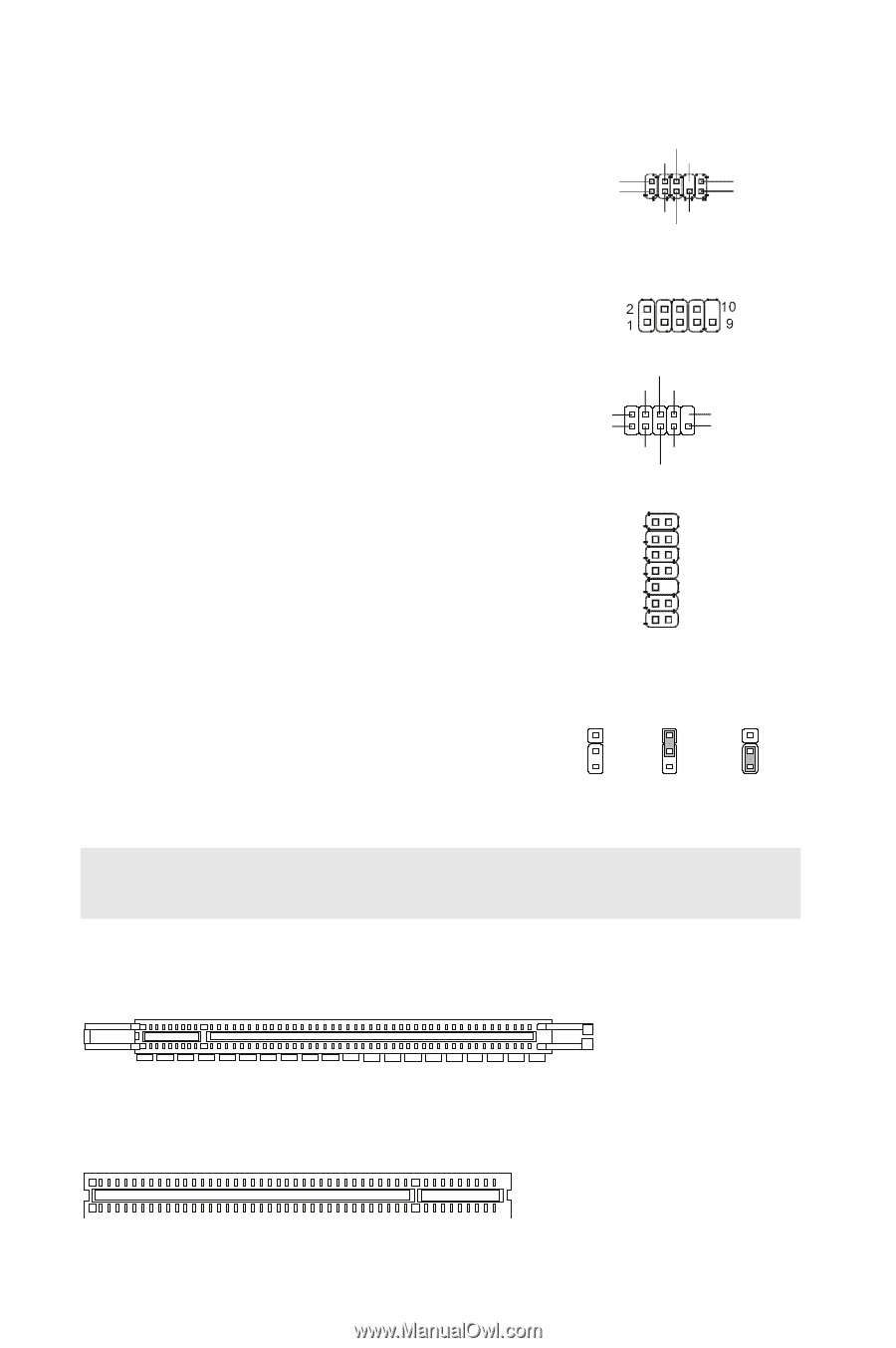
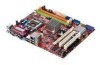
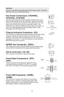
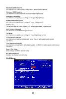
Front Panel Audio Connector: JAUD1 This connector allows you to connect the front panel audio and is compliant with Intel® Front Panel I/O Connectivity Design Guide. (2)GND (1)MIC_L MIC2_JD VCC5 NC Li ne _J D (1 0) Line-out_L(9) MIC_R Front to Sense Li ne -o ut _R SPI Debugging Connector: JSPI1 This connector is for internal debugging only. Serial Port Connector: JCOM1 This connector is a 16550A high speed communication port that sends/receives 16 bytes FIFOs. You can attach a serial device to it. TPM Module connector: JTPM1(Optional) This connector connects to a TPM (Trusted Platform Module) module. Please refer to the TPM security platform manual for more details and usages. DSR DTR CTS (2) SIN (1) DC D Key,no pin (10) R I (9) SOUT RTS GND 12 LCLK 3Vdual/ 3V_STB LRST# LAD0 VCC3 SIRQ LAD1 LAD2 LAD3 LFRAME# VCC5 KEY GND GND 13 14 Clear CMOS Jumper: JBAT1 There is a CMOS RAM onboard that has a power supply 1 from an external battery to keep the data of system 2 configuration. With the CMOS RAM, the system can 3 automatically boot OS every time it is turned on. If you want to clear the system configuration, set the jumper to clear data. 1 2 3 Keep Data 1 2 3 Clear Data Important: You can clear CMOS by shorting 2-3 pin while the system is off. Then return to 1-2 pin position. Avoid clearing the CMOS while the system is on; it will damage the mainboard. PCI (Peripheral Component Interconnect) Express Slot The PCI Express slot supports the PCI Express interface expansion card. The PCI Express x 16 slot supports up to 4.0 GB/s transfer rate. PCI (Peripheral Component Interconnect) Slot 8
-
 1
1 -
2
-
3
-
4
-
5
-
6
-
7
-
8
-
 9
9 -
 10
10 -
 11
11 -
 12
12 -
 13
13 -
 14
14 -
 15
15 -
 16
16 -
 17
17 -
 18
18 -
 19
19 -
20
-
21
-
22
-
23
-
24
-
25
-
26
-
27
-
28
-
29
-
30
-
31
-
32
-
33
-
34
-
35
-
36
-
37
-
38
-
39
-
40
-
41
-
42
-
43
-
44
-
45
-
46
-
47
-
48
-
49
-
50
-
51
-
52
-
53
-
54
-
55
-
56
-
57
-
58
-
59
-
60
-
61
-
62
-
63
-
64
-
65
-
66
-
67
-
68
-
69
-
70
-
71
-
72
-
73
-
74
-
75
-
76
-
77
-
78
-
79
-
80
-
81
-
82
-
83
-
84
-
85
-
86
-
87
-
88
-
89
-
90
-
91
-
92
-
93
-
94
-
95
 |
 |