MSI MS-7512-010 User Guide
MSI MS-7512-010 - P45 Zilent Motherboard Manual
 |
UPC - 816909045635
View all MSI MS-7512-010 manuals
Add to My Manuals
Save this manual to your list of manuals |
MSI MS-7512-010 manual content summary:
- MSI MS-7512-010 | User Guide - Page 1
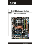
P45 Platinum Series MS-7512 (v1.X) Mainboard G52-75121X1 i - MSI MS-7512-010 | User Guide - Page 2
Support If a problem arises with your system and no solution can be obtained from the user's manual, please contact your place of purchase or local distributor. Alternatively, please try the following help resources for further guidance. Visit the MSI website for FAQ, technical guide, BIOS updates - MSI MS-7512-010 | User Guide - Page 3
1. Always read the safety instructions carefully. 2. Keep this User's Manual for future reference. 3. Keep this . 11. If any of the following situations arises, get the equipment checked by a service personnel: † The power cord or plug is damaged. † Liquid has penetrated into the equipment - MSI MS-7512-010 | User Guide - Page 4
if not installed and used in accordance with the instructions, may cause harmful interference to radio communications. However, limits. VOIR LANOTICE D'INSTALLATIONAVANT DE RACCORDER AU RESEAU. Micro-Star International MS-7512 This device complies with Part 15 of the FCC Rules. Operation is subject - MSI MS-7512-010 | User Guide - Page 5
WEEE (Waste Electrical and Electronic Equipment) Statement v - MSI MS-7512-010 | User Guide - Page 6
vi - MSI MS-7512-010 | User Guide - Page 7
vii - MSI MS-7512-010 | User Guide - Page 8
...ii Revision History ...ii Technical Support ...ii Safety Instructions ...iii FCC-B Radio Frequency Interference Statement iv W EEE (Waste Electrical and Electronic Equipment) Statement v Chapter 1. Getting Started 1-1 Mainboard Specifications 1-2 Mainboard Layout 1-4 Packing Checklist - MSI MS-7512-010 | User Guide - Page 9
DOT (Dynamic OverClocking B-5 Clock ...B-6 Voltage ...B-7 FAN Speed ...B-8 Temperature ...B-9 User Profile ...B-10 Appendix C Intel ICH10R SATA RAID C-1 ICH10R Introduction C-2 BIOS Configuration C-3 Installing Driver ...C-9 Installing Software C-11 RAID Migration Instructions C-16 Recovery - MSI MS-7512-010 | User Guide - Page 10
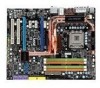
Getting Started Chapter 1 Getting Started Thank you for choosing the P45 Platinum Series (MS7512 v1.X) ATX mainboard. The P45 Platinum Series mainboards are based on Intel® P45 & ICH10R chipsets for optimal system efficiency. Designed to fit the advanced Intel® CoreTM 2 Extreme/Quad/Duo, Pentinum® - MSI MS-7512-010 | User Guide - Page 11
visit http://global. m si. c om . t w / index. php?func =c puform ) Chipset - North Bridge: Intel® P45 chipset - South Bridge: Intel® ICH10R chipset Memory Support - 4 DDR2 DIMMs support DDR2 1200**(OC) / 1066 / 800 (16GB Max) (To support 16GB Max, please check the criteria of Intel website.) **(For - MSI MS-7512-010 | User Guide - Page 12
-out pinheader - 1 CD-in connector - 1 front audio pinheader - 1 front panel connector - 1 serial pinheader - 1 TPM Module connector - 1 GreenPower Genie connector TPM - Supports TPM Slots - 2 PCI Express x16 slots compatible with PCIE 2.0 spec a. for CrossFire mode, please install both graphics - MSI MS-7512-010 | User Guide - Page 13
PCI_E1 PCI_E2 JB2 JB1 PCI_E3 PCI_E4 Intel P45 JSPI1 JCI1 JBAT1 Intel ICH10R SATA7 SATA8 IDE 1 SATA5-6 SATA2-4 SATA1-3 ALC888 PCI1 PCI2 JAUD1 JCD1 B AT T + RESET JSPDO1 J1394_1 JFP2 JFP1 JUSB3 JUSB2 PWRBTN JUSB1 JTPM1 JC OM1 P45 Platinum Series (MS-7512 v1.X) ATX Mainboard 1-4 - MSI MS-7512-010 | User Guide - Page 14
Packing Checklist Getting Started MSI motherboard MSI Driver/Utility CD Back IO Shield Power Cable SATA Cable IDE Cable Floppy Cable external SATA Cable (Optional) 1394+USB Bracket (optional) User's Guide and Quick Guide GreenPower Genie Set (optional) * The pictures are for reference - MSI MS-7512-010 | User Guide - Page 15
Hardware Setup Chapter 2 Hardware Setup This chapter provides you with the information about hardware setup procedures. While doing the installation, be careful in holding the components and follow the installation procedures. For some components, if you install in the wrong orientation, the - MSI MS-7512-010 | User Guide - Page 16
MS-7512 Mainboard Quick Components Guide SYSFAN2, p.2-14 JCI1, CPU, p.2-3 p.2-14 POWER1, p.2-9 SYSFAN1, p.2-14 JSPI1, p.2-16 CPUFAN1, p.2-14 SYSFAN5, p.2-14 DIMMs, p.2-7 Back Panel, p.2-10 JPWR1, p.2-9 PCI_E, p.2-23 PCI, p.2-24 JAUD1, p.2-17 - MSI MS-7512-010 | User Guide - Page 17
first to ensure the safety of CPU. Overclocking This mainboard is designed to support overclocking. However, please make sure your components are able to tolerate such abnormal setting, while doing overclocking. Any attempt to operate beyond product specifications is not recommended. We do not - MSI MS-7512-010 | User Guide - Page 18
MS-7512 Mainboard CPU & Cooler Installation W hen you are installing the CPU, make sure the CPU has a cooler attached on the top to prevent overheating. Meanwhile, do - MSI MS-7512-010 | User Guide - Page 19
Hardware Setup 5. Lift the load lever up and open the load plate. 6. After confirming the CPU direction for correct mating, put down the CPU in the socket housing frame. Be sure to grasp on the edge of the CPU base. Note that the alignment keys are matched. alignment key 7. Visually inspect if - MSI MS-7512-010 | User Guide - Page 20
MS-7512 Mainboard 9. Press down the load lever lightly onto the load mainboard to confirm that the clip-ends are correctly inserted. locking switch Important 1. Read the CPU status in BIOS (Chapter 3). 2. Whenever CPU is not installed, always protect your CPU socket pin with the plastic cap - MSI MS-7512-010 | User Guide - Page 21
. For more information on compatible components, please visit http://global.msi.com. tw/index.php?func=testreport DDR2 240-pin, 1.8V 56x2=112 pin 64x2=128 pin Dual-Channel Memory Population Rules In Dual-Channel mode, the memory modules can transmit and receive data with two data bus lines - MSI MS-7512-010 | User Guide - Page 22
. Important You can barely see the golden finger if the memory module is properly inserted in the DIMM slot. 3. Manually check if the memory module has been locked in place by the DIMM slot clips at the sides. Volt Notch Important - DDR2 memory modules are not interchangeable with DDR and the - MSI MS-7512-010 | User Guide - Page 23
Hardware Setup Power Supply ATX 24-Pin Power Connector: ATX1 This connector allows you to connect an ATX 24-pin power supply. To connect the ATX 24-pin power supply, make sure the plug of the power supply is inserted in the proper orientation and the pins are aligned. Then push down the power - MSI MS-7512-010 | User Guide - Page 24
MS-7512 Philips Digital Interconnect Format) connector is provided for digital audio transmission to external speakers through an optical fiber cable. USB LAN The standard RJ-45 LAN jack is for connection to the Local Area Network (LAN). You can connect a network cable to it. Yellow Green - MSI MS-7512-010 | User Guide - Page 25
(Blue) - Line In is used for external CD player, tapeplayer or other audio devices. Line-Out (Green) - Line Out, is a connector for speakers There is a CMOS RAM on board that has a power supply from external battery to keep the system configuration data. With the CMOS RAM, the system can - MSI MS-7512-010 | User Guide - Page 26
MS-7512 Mainboard Connectors Floppy Disk Drive Connector: FDD1 This connector supports 360KB, 720KB, 1.2MB, 1.44MB or 2.88MB floppy disk drive. FDD1 IDE Connector: IDE1 This connector supports IDE hard disk to IDE device's documentation supplied by the vendors for jumper setting instructions. 2-12 - MSI MS-7512-010 | User Guide - Page 27
speed Serial ATA interface port. Each connector can connect to one Serial ATA device. SATA1-3 SATA2-4 SATA5-6 SATA1~6supported by ICH10R SATA7 SATA8 supported by JMicron 363 Important Please do not fold the Serial ATA cable into 90-degree angle. Otherwise, data loss may occur during transmission - MSI MS-7512-010 | User Guide - Page 28
MS-7512 Mainboard Fan Power Connectors: CPUFAN1, SYSFAN1~5 The fan power connectors support system cooling fan with +12V. W hen connecting the wire to the connectors message on the screen. To clear the warning, you must enter the BIOS utility and clear the record. CINTRU GND 2-14 1 2 JCI1 - MSI MS-7512-010 | User Guide - Page 29
) connect the GREEN connector to J1394_1 S/PDIF-Out Connector: JSPDO1 This connector is used to connect S/PDIF (Sony & Philips Digital Interconnect Format) interface for digital audio transmission. JSPDO1 VCC GND SPDIF S/PDIF Bracket (Optional) 2-15 - MSI MS-7512-010 | User Guide - Page 30
MS-7512 Mainboard JSPI Debugging Pin Header: JSPI1 The pin header is for internal debugging only. JSPI1 to a TPM (Trusted Platform Module) module (optional). Please refer to the TPM security platform manual for more details and usages. 2 14 1 13 Pin Signal Description 1 LCLK LPC clock 3 - MSI MS-7512-010 | User Guide - Page 31
Connector: JAUD1 This connector allows you to connect the front panel audio and is compliant with Intel® Front Panel I/O Connectivity Design Guide. 2 1 10 9 JAUD1 PIN SIGNAL 1 MIC_L 2 GND 3 MIC_R 4 PRESENCE# 5 LINE out_R 6 MIC_JD 7 Front_JD 8 NC 9 LINE out_L 10 LINEout_JD - MSI MS-7512-010 | User Guide - Page 32
MS-7512 Mainboard Front Panel Connectors: JFP1, JFP2 These connectors are for electrical connection to the front panel switches and LEDs. The JFP1 is compliant with Intel® Front Panel I/O Connectivity Design Guide. PIN Power Power LED Switch 1 +- 2 JFP1 2 1 10 3 9 4 +- -+ 5 HDD Reset - MSI MS-7512-010 | User Guide - Page 33
Front USB Connector: JUSB1 ~ 3 These connectors, compliant with Intel® I/O Connectivity Design Guide, is ideal for connecting high-speed USB interface peripherals such as USB HDD, digital cameras Genie (optional). Please refer to the GreenPower Genie manual for more details and usages. J2 2-19 - MSI MS-7512-010 | User Guide - Page 34
MS-7512 Mainboard Jumper The motherboard provides the following jumper for you to set the computer's function. This section will explain how to change your motherboard's function through the use of jumper. Hardware Overclock FSB Jumpers: JB1, JB2 (optional) You can overclock the FSB to increase the - MSI MS-7512-010 | User Guide - Page 35
onboard that has a power supply from an external battery to keep the data of system configuration. W ith the CMOS RAM, the system can automatically boot OS every time it is turned on. If you want to clear the system configuration, set the jumper to clear - MSI MS-7512-010 | User Guide - Page 36
MS-7512 Mainboard Button The motherboard provides the following button for you to set the computer's function. This section will explain how to change your motherboard's function through the use of button. Power Button: POWER This power button is used to turn-on or turn-off the system. Press the - MSI MS-7512-010 | User Guide - Page 37
supports up to 8.0 GB/s transfer rate. The PCI Express x1 supports up to 250 MB/s transfer rate. PCI Express x16 Slots support up to PCI Express 2.0x16 speed (PCI_E1 & PCI_E4) White PCI Express x 1 Slot supports settings for the expansion card, such as jumpers, switches or BIOS configuration. 2-23 - MSI MS-7512-010 | User Guide - Page 38
MS-7512 Mainboard PCI (Peripheral Component Interconnect) Slot The PCI slot supports LAN card, SCSI card, USB card, and other add-on cards that comply with PCI specifications for the expansion card, such as jumpers, switches or BIOS configuration. PCI Interrupt Request Routing The IRQ, acronym of - MSI MS-7512-010 | User Guide - Page 39
't have to enable the CrossFire in BIOS by yourself. Following the process below two graphics cards are of the same brand and specifications; b. these two cards are installed on both Service Pack 2 (SP2)& Windows® XP Profes -sional x64 Edition & Windows® Vista support the CrossFire function. 2-25 - MSI MS-7512-010 | User Guide - Page 40
MS-7512 Mainboard 3.W hen all of the hardware and software has been properly set up and installed, reboot the system. After modes: • SuperTiling • Scissor Mode • Alternate Frame Rendering • Super Anti-aliasing. for more details, please consult the graphics card manual from the manufacturer. 2-26 - MSI MS-7512-010 | User Guide - Page 41
LED Status Indicators Hardware Setup LED28 LED29 LED1 LED2 LED4 LED5 LED6 LED9 LED21,22,23,24,25 LED27 LED26 LED3 LED12,13 LED 8,7 LED14,10 L E D 1 5 , 11 LED16 2-27 - MSI MS-7512-010 | User Guide - Page 42
MS-7512 Mainboard Name Status LED16 Lights when system is on standby mode. LED3 phase power mode. LED25 Lights when CPU is in 1 phase power mode. LED26 Lights when memory is in 2 phase power mode. LED27 Lights when memory is in 1 phase power mode. LED28 Lights when North Bridge is in 1 phase power - MSI MS-7512-010 | User Guide - Page 43
users to identify system problems through 16 various Chipset Initialization Group4 Group3 Group2 Group1 MemoryDetection Test Testing onboard memory size. The D-LED will hang if the memory module is damaged or not installed properly. Group4 Group3 Group2 Group1 Decompressing BIOS image to RAM - MSI MS-7512-010 | User Guide - Page 44
This chapter provides information on the BIOS Setup program and allows you to configure the system for optimum use. You may need to run the Setup program when: ² An error message appears - MSI MS-7512-010 | User Guide - Page 45
digit refers to BIOS maker as A = AMI, W = AWARD, and P = PHOENIX. 2nd - 5th digit refers to the model number. 6th digit refers to the chipset as I = Intel, N = nVidia, and V = VIA. 7th - 8th digit refers to the customer as MS = all standard customers. V1.1 refers to the BIOS version. 030807 refers - MSI MS-7512-010 | User Guide - Page 46
BIOS Setup Control Keys Enter> Move to the sub-menu. If you want to return to the main menu, just press the . General Help The BIOS setup program provides a General Help screen. You can call up this screen from any menu by simply pressing . The - MSI MS-7512-010 | User Guide - Page 47
. PNP/PCI Configurations This entry appears if your system supports PnP/PCI. H/W Monitor This entry shows your PC health status. BIOS Setting Password Use this menu to set the password for BIOS. Cell Menu Use this menu to specify your settings for frequency/voltage control and overclocking. 3-4 - MSI MS-7512-010 | User Guide - Page 48
-Safe Defaults Use this menu to load the default values set by the BIOS vendor for stable system performance. Load Optimized Defaults Use this menu to load the default values set by the mainboard manufacturer specifically for optimal performance of the mainboard. Save & Exit Setup Save changes to - MSI MS-7512-010 | User Guide - Page 49
MS-7512 Mainboard Standard CMOS Features The items in Standard CMOS Features Menu includes The format is . day Day of the week, from Sun to Sat, determined by BIOS. Read-only. month The month from Jan. through Dec. date The date from 1 to 31 can be keyed by numeric - MSI MS-7512-010 | User Guide - Page 50
BIOS Setup Device / Vender / Size It will showing the device information that you connected to the SATA connector. LBA/Large M ode This allows you to enable or disable the LBA Mode. Setting to Auto enables LBA mode if the device supports it and the devices is not already formatted with LBA mode - MSI MS-7512-010 | User Guide - Page 51
MS-7512 Mainboard System Information Press to enter the sub-menu, and the following screen appears. This sub-menu shows the CPU information, BIOS version and memory status of your system (read only). 3-8 - MSI MS-7512-010 | User Guide - Page 52
when you need to disable it is when you want to update the BIOS. After updating the BIOS, you should immediately re-enable it to protect it against viruses Advanced Programmable Interrupt Controller). Due to compliance with PC2001 design guide, the system is able to run in APIC mode. Enabling APIC - MSI MS-7512-010 | User Guide - Page 53
MS-7512 Mainboard MPS Table Version This field allows you to select which MPS (Multi-Processor Specification) version to be used for the operating system. You need to select the MPS version supported by your operating system. To find out which version to use, consult the vendor of your operating - MSI MS-7512-010 | User Guide - Page 54
BIOS Setup HPET The HPET (High Precision Event Timers) is a component that is part of the chipset. You can to enable it, Press to enter the sub-menu and the following screen appears: TCG/TPM SUPPORT This field is used to enable or disable TPM (Trusted Platform Module). Clearing the TPM - MSI MS-7512-010 | User Guide - Page 55
MS-7512 Mainboard Integrated Peripherals USB Controller This setting allows you to enable/disable the onboard USB controller. USB Device Legacy Support Select [Enabled] if you need to use a USB-interfaced device in the operating system. Onboard LAN Controller This item is used to enable/disable the - MSI MS-7512-010 | User Guide - Page 56
audio controller. On-Chip ATA Devices Press to enter the sub-menu and the following screen appears: PCI IDE BusMaster This item allows you to enable/ disable BIOS or disable the SATA controller. RAID Mode This item is used to enable/disable the RAID function for SATA devices. I/O Device - MSI MS-7512-010 | User Guide - Page 57
MS-7512 Mainboard Power Management Setup Important S3-related functions described in this section are available only when your BIOS supports this state, no system context is lost (CPU or chipset) and hardware maintains all system context. [S3] The main memory that remains powered while most other hardware - MSI MS-7512-010 | User Guide - Page 58
menu appears. Wake Up Event By The item allows you to wake up event by BIOS or OS. Resume From S3 By USB Device The item allows the activity of the USB device to wake up the system from S3 (Suspend to RAM) sleep state. Resume From S3 By PS/2 Keyboard This setting determines whether the - MSI MS-7512-010 | User Guide - Page 59
MS-7512 Mainboard H/W Monitor Chassis Intrusion The field enables or disables the feature of can control the CPU fan speed automatically depending on the current temperature to keep it with in a specific range. You can select a fan target value here. If the current CPU fan temperature reaches to the - MSI MS-7512-010 | User Guide - Page 60
BIOS Setup BIOS Setting Password W hen you select this function, a message as below will appear on the screen: Type the password, up to six characters in length, and press . The password typed now will replace any previously set password from CMOS memory. You will be prompted to confirm the - MSI MS-7512-010 | User Guide - Page 61
MS-7512 Mainboard Cell Menu Important Change these settings only if you are familiar with the chipset. Current CPU / DRAM Frequency These items show the current clocks of CPU and Memory speed. Read-only. Energy Save Press to enter the sub-menu and the following screen appears. 3-18 - MSI MS-7512-010 | User Guide - Page 62
to enhance the overall performance. Important Even though the Dynamic Overclocking Technology is more stable than manual overclocking, basically, it is still risky. We suggest user to make sure that your CPU / memory modules can afford to overclocking regularly first. If you find the PC appears to - MSI MS-7512-010 | User Guide - Page 63
MS-7512 Mainboard Advance DRAM Configuration Press to enter the sub-menu and the following screen appears. Configuration DRAM Timing by SPD Setting to [Enabled] enables DRAM CAS# Latency automatically to be determined by BIOS based on the configurations on the SPD (Serial Presence Detect) - MSI MS-7512-010 | User Guide - Page 64
BIOS Setup tWR W hen the Configuration DRAM Timing by SPD is set to [Manual], the field is adjustable. It the write buffers can be written to the memory cells before precharge occurs. tWTR W hen the Configuration DRAM Timing by SPD is set to [Manual], the field is adjustable. This item controls - MSI MS-7512-010 | User Guide - Page 65
(V) These items dispaly the power status of Memory, FSB and chipset. Read-only. Spread Spectrum W hen the motherboard's clock generator pulses, the extreme values ( which may just cause your overclocked processor to lock up. Important 1. If you do not have any EMI problem, leave the setting at [ - MSI MS-7512-010 | User Guide - Page 66
. Important 1. CPU Speed = CPU Frequency * CPU Ratio 2. This motherboard supports overclocking greatly. However, please make sure your peripherals and components are bearable for some special settings. Any operation that exceeds product specification is not recommended. Any risk or damge resulting - MSI MS-7512-010 | User Guide - Page 67
MS-7512 Mainboard User Setting Save Settings 1/ 2 These items are used to save the settings set by yourself to CMOS. Load Settings 1/ 2 These items are available after you save your settings in Save Settings 1/ 2 items , and are used to load the settings from CMOS. 3-24 - MSI MS-7512-010 | User Guide - Page 68
The two options on the main menu allow users to restore all of the BIOS settings to the default Fail-Safe or Optimized values. The Optimized Defaults are the default values set by the mainboard manufacturer specifically for optimal performance of the mainboard. The Fail-Safe Defaults are the default - MSI MS-7512-010 | User Guide - Page 69
Realtek ALC888/888T Audio Appendix A Realtek ALC888/888T Audio The Realtek ALC888/888T provides 10-channel DAC that simultaneously supports 7.1 sound playback and 2 channels of independent stereo sound output (multiple streaming) through the Front-Out-Left and Front-OutRight channels. A-1 - MSI MS-7512-010 | User Guide - Page 70
MS-7512 Mainboard Installing the Realtek HD Audio Driver You need to install the driver for Realtek ALC888/888T codec to function properly before you can get access to 2-, 4-, 6-, 8- channel or 7.1+2 channel audio operations. Follow the procedures described below to install the drivers for different - MSI MS-7512-010 | User Guide - Page 71
Realtek ALC888/888T Audio 3. Click Next to install the Realtek High Definition Audio Driver. 4. Click Finish to restart the system. Click here Select this option Click here A-3 - MSI MS-7512-010 | User Guide - Page 72
MS-7512 Mainboard Software Configuration After installing the audio driver, you are able to use the 2-, 4-, 6- or 8- channel audio feature now. Click the audio icon from the system tray at the lower-right corner of the screen to activate the HD Audio Configuration. It is also available to enable the - MSI MS-7512-010 | User Guide - Page 73
the arrow, totally 23 kinds of sound effect will be shown for selection. Realtek HD Audio Sound Manager also provides five popular settings "Stone Corridor", "Bathroom", "Sewer pipe", "Arena" and "Audio Corridor" for quick enjoyment. You may choose the provided sound effects, and the equalizer will - MSI MS-7512-010 | User Guide - Page 74
MS-7512 Mainboard Equalizer Selection Equalizer frees users from default settings; users may create their owned preferred settings by utilizing this tool. 10 bands of equalizer, ranging - MSI MS-7512-010 | User Guide - Page 75
Frequently Used Equalizer Setting Realtek recognizes the needs that you might have. By leveraging our long experience at audio field, Realtek HD Audio Sound Manager provides you certain optimized equalizer settings that are frequently used for your quick enjoyment. [How to Use It] Other than the - MSI MS-7512-010 | User Guide - Page 76
MS-7512 Mainboard Mixer In the Mixer part, you may adjust the volumes of the rear and front panels individually. 1. Adjust Volume You can adjust the volume of the speakers that you pluged in front or rear panel by select the Realtek HD Audio rear output or Realtek HD Audio front output items. - MSI MS-7512-010 | User Guide - Page 77
will be played from the rear panel, which is the default setting. Then you must to select the Realtek HD Audio front output from the scroll list first, and use a different program to play the second audio source (for example: use Winamp to play MP3 files). You will find that the second - MSI MS-7512-010 | User Guide - Page 78
MS-7512 Mainboard 3. Playback control Tool Mute Playback device This function is to let you freely decide which ports to output the sound. And this is essential when multistreamingplayback enabled. - Realtek HD Audio Rear Output - Realtek HD Audio Front Output Mute You may choose to mute single - MSI MS-7512-010 | User Guide - Page 79
Mute Recording device -Back Line in/Mic, Front Lin in -Realtek HD Audio Input Mute You may choose to mute single or multiple volume controls or to completely mute sound input. Tool - Show the following volume controls This - MSI MS-7512-010 | User Guide - Page 80
MS-7512 Mainboard Audio I/O In this tab, you can easily configure your multi-channel audio function and speakers. You can choose a desired multi-channel operation here. a. as your device. - If not correct, Realtek HD Audio Manager will guide you to plug the device into the correct jack. a A-12 - MSI MS-7512-010 | User Guide - Page 81
Realtek ALC888/888T Audio Connector Settings Click to access connector settings. Disable front panel jack detection (option) Find no function on front panel jacks? Please check if front jacks - MSI MS-7512-010 | User Guide - Page 82
MS-7512 Mainboard S/PDIF Short for Sony/Philips Digital Interface, a standard audio file transfer format. S/PDIF allows the transfer of digital audio signals from one device to another without having to be converted first to an analog format. Maintaining the viability of a digital signal prevents - MSI MS-7512-010 | User Guide - Page 83
Realtek ALC888/888T Audio Test Speakers You can select the speaker by clicking it to test its functionality. The one you select will light up and make testing sound. - MSI MS-7512-010 | User Guide - Page 84
MS-7512 Mainboard Microphone In this tab you may set the function of the microphone. Select the Noise Suppression to remove the possible noise during recording, or - MSI MS-7512-010 | User Guide - Page 85
Realtek ALC888/888T Audio 3D Audio Demo In this tab you may adjust your 3D positional audio before playing 3D audio applications like gaming. You may also select different environment to choose the most suitable environment you like. A-17 - MSI MS-7512-010 | User Guide - Page 86
MS-7512 Mainboard Information In this tab it provides some information about this HD Audio Configuration utility, including Audio Driver Version, DirectX Version, Audio Controller & Audio Codec. You may also select the language of this utility by choosing from the Language list. Also there is a - MSI MS-7512-010 | User Guide - Page 87
Hardware Setup Connecting the Speakers W hen you have set the Multi-Channel Audio Function mode properly in the software utility, connect your speakers to the correct phone jacks in accordance with the setting in software utility. n 2-Channel Mode - MSI MS-7512-010 | User Guide - Page 88
MS-7512 Mainboard n 4-Channel Mode for 4-Speaker Output 1 4 2 5 3 6 4-Channel Analog Audio Output 1 Line In 2 Line Out (Front channels) 3 MIC 4 Line Out (Rear channels) 5 No function 6 No function a A-20 - MSI MS-7512-010 | User Guide - Page 89
Realtek ALC888/888T Audio n 6-Channel Mode for 6-Speaker Output 1 4 2 5 3 6 6-Channel Analog Audio Output 1 Line In 2 Line Out (Front channels) 3 MIC 4 Line Out (Rear channels) 5 Line Out (Center and Subwoofer channel) 6 No function A-21 - MSI MS-7512-010 | User Guide - Page 90
MS-7512 Mainboard n 8-Channel Mode for 8-Speaker Output 1 4 2 5 3 6 8-Channel Analog Audio Output 1 Line In 2 Line Out (Front channels) 3 MIC 4 Line Out (Rear channels) 5 Line Out (Center and Subwoofer channel) 6 Line Out (Side channels) Important To enable 7.1 channel audio-out function on - MSI MS-7512-010 | User Guide - Page 91
develop, helps users to monitor or configure the hardware status of MSI Mainboard & MSI Graphics card in windows, such as CPU/GPU clock, voltage, XP/ Sempron or compatible CPU with PCI Express slot. 2. 256MB system memory. 3. CD-ROM drive for software installation. 4. Operation system: W indows XP. - MSI MS-7512-010 | User Guide - Page 92
MS-7512 Mainboard Activating Dual Core Center Once you have your Dual Core Center installed (locate the setup source file in the setup CD accompanying with your mainboard, path: Utility --> MSI Utility --> Dual Core Center), it will have an icon in the system tray, a short cut icon on the - MSI MS-7512-010 | User Guide - Page 93
the MSI V044 (V044 has to install with the version 8.26 or newer driver)/ V046 or V060 graphics card can activate the full function of this utility. If you install a graphics card of other brand, only hardware status of the MSI memory clock of graphics card will show below. DOT - MSI MS-7512-010 | User Guide - Page 94
MS-7512 Mainboard AV/ Game/ Office/ Silence/ Cool MSI provides five common settings for different environments. The settings had been set to optimal values to reach better performance in each environment. Click the button - MSI MS-7512-010 | User Guide - Page 95
, it will speed up the GPU, memory, fan and voltage automatically to make the Overclocking Technology will be powered only when users' PC runs huge amount of data, like 3D games or video process, and the motherboard Dynamic Overclocking Technology is more stable than manual overclocking, basically, it - MSI MS-7512-010 | User Guide - Page 96
MS-7512 Mainboard Clock In the Clock sub-menu, you can see clock status (including FSB/ CPU clock of mainboard and GPU/ memory clock of graphics card) of your system. And you can select desired value for overclocking. There will be several items for you to select for overclocking after you - MSI MS-7512-010 | User Guide - Page 97
Voltage I In the Voltage sub-menu, you can see voltage status (including Vcore, memory, GPU voltage... etc.) of your system, and you can select desired value for overclocking. It will show several items to select for overclocking after you click the button. You can click the plus sign button to - MSI MS-7512-010 | User Guide - Page 98
MS-7512 Mainboard FAN Speed In the FAN Speed sub-menu, you can read fan with red color will be shown. Important 1. When you set the fan speed manually, please make sure to disabled the "CPU Smart FAN Target" item in the BIOS. 2. In the user profile, clicking the Save button can save the changes - MSI MS-7512-010 | User Guide - Page 99
Dual Core Center Temperature In the Temperature sub-menu, you can see temperature status of your system. On the underside, it shows the graphs of the temperatures. Only the curves of the item which the button is lit up with red color will be shown. B-9 - MSI MS-7512-010 | User Guide - Page 100
MS-7512 Mainboard User Profile In the User Profile sub-menu, click the setting button that besides the user profile bar, and the next screen will appear. - MSI MS-7512-010 | User Guide - Page 101
Dual Core Center Use the draw bar to set the max system temperature. W hen the system temperature exceeds the threshold you defined, the system will pop up a warning message and shut down the system. Use the draw bar to set the minimal fan speed. When the fan speed is lower than the threshold you - MSI MS-7512-010 | User Guide - Page 102
Intel ICH10R SATA RAID Appendix C Intel ICH10R SATA RAID This appendix will assist users in configuring and enabling RAID functionality on platforms C-1 - MSI MS-7512-010 | User Guide - Page 103
MS-7512 Mainboard ICH10R Introduction The ICH10R provides a hybrid solution that combines 6 independent SATAII ports for support of up to 6 Serial ATAII (Serial ATAII RAID) drives. Serial ATAII (SATAII) is the latest generation of the ATA interface. SATA hard drives deliver blistering transfer - MSI MS-7512-010 | User Guide - Page 104
Intel Matrix Storage Manager Option ROM should be integrated with the system BIOS on all motherboards with a supported Intel chipset. The Intel Matrix Stroage Manager Option ROM is the Intel RAID implementation and provides BIOS and DOS disk services. Please use + keys to enter the "Intel - MSI MS-7512-010 | User Guide - Page 105
MS-7512 Mainboard After pressing the and keys simultaneously, the following window will appear: (1) Create RAID Volume 1. Select option 1 "Create RAID Volume" and press key. The following screen appears. Then in the Name field, specify a RAID Volume name and then press the - MSI MS-7512-010 | User Guide - Page 106
and the following screen appears. Use key to select the disks you want to create for the RAID volume, then click key to finish selection. 4. Then select the strip value for the RAID array by using the "upper arrow" or "down arrow" keys to scroll through the available values, and - MSI MS-7512-010 | User Guide - Page 107
MS-7512 Mainboard Important Since you want to create two volumes (Intel Matrix RAID Technology), this default size (maximum) needs to be reduced. for you to confirm if you are sure to create the RAID volume. Press to continue. 7. Then the following screen appears to indicate that the creation - MSI MS-7512-010 | User Guide - Page 108
volume, but please be noted that all data on RAID drives will be lost. Important If your system currently boots to RAID and you delete the RAID volume in the Intel RAID Option ROM, your system will become unbootable. Select option 2 Delete RAID Volume from the main menu window and press key - MSI MS-7512-010 | User Guide - Page 109
MS-7512 Mainboard (3) Reset Disks to Non-RAID Select option 3 Reset Disks to Non-RAID and press to delete the RAID volume and remove any RAID structures from the drives. The following screen appears: Press key to accept the selection. Important 1. You will lose all data on the RAID - MSI MS-7512-010 | User Guide - Page 110
Intel ICH10R SATA RAID (4) Recovery Volume Options Select option 4 Recovery Volume Options and press to change recovery volume mode. The following screen appears: Recovery mode will change from Continuous Update to On-Request after you enable Only Recovery Disk or Only Master Disk. C-9 - MSI MS-7512-010 | User Guide - Page 111
MS-7512 Mainboard Installing Driver Install Driver in Windows Vista / XP / 2000 † New Windows Vista / XP / 2000 Installation The following details the installation of the drivers Please follow the instruction below to make an "Intel® RAID Driver" for yourself. 1. Insert the MSI CD into the CD - MSI MS-7512-010 | User Guide - Page 112
Intel ICH10R SATA RAID † Existing Windows Vista/XP/2000 Driver Installation 1. Insert the MSI CD into the CD-ROM drive. 2. The CD will auto-run and the setup screen will appear. 3. Under the Driver tab, click on Intel IAA RAID Edition. 4. The drivers will be automatically installed. † Confirming - MSI MS-7512-010 | User Guide - Page 113
MS-7512 Mainboard Installing Software Install Intel Matrix Storage Console The Intel Application Accelerator RAID Edition driver may be used to operate the hard drive from which the system is booting or a hard drive that contains important data. For this reason, you - MSI MS-7512-010 | User Guide - Page 114
Intel ICH10R SATA RAID The InstallShield Wizard will begin automatically for installation showed as following: Click on the Next button to proceed the installation in the welcoming window. C-13 - MSI MS-7512-010 | User Guide - Page 115
MS-7512 Mainboard The window shows the components to be installed. Click Next button to continue. After reading the license agreement in the following window, click Yes button to continue. C-14 - MSI MS-7512-010 | User Guide - Page 116
Intel ICH10R SATA RAID The following window appears to show the Readme File Information. It shows the system requirements and installation information. Once the installation is complete, the following window appears. C-15 - MSI MS-7512-010 | User Guide - Page 117
MS-7512 Mainboard RAID Migration Instructions The Intel Matrix Storage Console offers the flexibility to upgrade from a single Serial ATA (SATA) hard drive to RAID configuration when an additional SATA hard drive is added to the system. This process will create a new RAID volume from an existing - MSI MS-7512-010 | User Guide - Page 118
Intel ICH10R SATA RAID Create RAID Volume from Existing Disk To create a RAID volume from an existing disk, choose Action --> Create RAID Volume from Existing Hard Drive. The Create RAID Volume from Existing Hard Drive Wizard pops up to lead you for the following procedure. Click Next to continue. - MSI MS-7512-010 | User Guide - Page 119
MS-7512 Mainboard (1) Configure Volume Here you can configure the new RAID volume by entering the volume name, selecting the RAID level and strip size. † RAID Volume Name: A desired RAID volume name needs to be typed in where the 'RAID_Volume1' text currently appears above. The RAID volume name has - MSI MS-7512-010 | User Guide - Page 120
the correct parity information), or similar to RAID-1 writes. The write efficiency depends heavily on the amount of memory in the machine, and the usage pattern should choose the strip size value which is best suited to your specific RAID usage model. The most typical strip size settings are: 4KB: - MSI MS-7512-010 | User Guide - Page 121
MS-7512 Mainboard (3) Select Member Hard Drive(s) Then select the member disk (the target disk) that you wish to use and then click "-->" to move it to - MSI MS-7512-010 | User Guide - Page 122
amount in the space or use the slider to specify. It is recommended you use 100% of the available space for the optimized usage. For RAID 0 volume, if you do not specify 100% of the hard drive space, the rest hard drive space will be worked as - MSI MS-7512-010 | User Guide - Page 123
MS-7512 Mainboard (6) Start Migration The migration process may take up to two hours to complete depending on the size of the disks being used and the - MSI MS-7512-010 | User Guide - Page 124
Intel ICH10R SATA RAID Recovery Volume Creation A recovery volume can be created using either Basic mode or Advanced mode in the Intel Matrix Storage Console. Recovery Volume in Basic - MSI MS-7512-010 | User Guide - Page 125
MS-7512 Mainboard Recovery Volume in Advanced Mode Creation Important Creating a recovery volume will permanently delete any existing data on the drive selected as the recovery drive. - MSI MS-7512-010 | User Guide - Page 126
Intel ICH10R SATA RAID (6) Select a hard drive to be used as the master hard drive for the recovery volume. (7) Select a hard drive to be used as the recovery hard drive for the recovery volume. C-25 - MSI MS-7512-010 | User Guide - Page 127
MS-7512 Mainboard (8) Select an update policy. (9) Select Finish to begin recovery volume creation. C-26 - MSI MS-7512-010 | User Guide - Page 128
is powered off. 2. Replace the failed hard drive with a new one that is of equal or greater c ap ac i t y. 3. Reboot the system to Intel RAID Option ROM by press and keys simultaneously during the Power-On Self Test (POST). 4. Select the port of the destination disk for rebuilding, and - MSI MS-7512-010 | User Guide - Page 129
MS-7512 Mainboard 5. Exit Intel RAID Option ROM, and then reboot to W indows system. 6. W hen prompted to rebuild the RAID volume, click 'Yes'. 7. The Intel(R) Storage Utility will be launched. Right-click the new hard drive and select 'Rebuild to this Disk'. The 'Rebuild W izard' - MSI MS-7512-010 | User Guide - Page 130
Appendix D JMicron RAID Introduction This appendix will assist users in configuring and enabling RAID functionality on platforms The JMicron RAID solution supports RAID level 0 (striping), RAID level 1 (mirroring) and JBOD (C onc aten ate). Important - MSI MS-7512-010 | User Guide - Page 131
MS-7512 Mainboard Introduction JMicron JMB363 offers RAID level 0 (Striping), RAID level 1 (Mirroring and Duplexing) and JBOD (Concatenate). RAID 0 breaks the data into blocks which are written to separate hard drives. Spreading the hard drive I/O load across independent channels greatly improves - MSI MS-7512-010 | User Guide - Page 132
- Sovle a mirror conflict. Rebuild Mirror Drive - Rebuild data, when RAID 1 data mirroring is lost. Save And Exit Setup - Save all settings and exit the BIOS utility. Exit W ithout Saving - Exit the BIOS utiltiy without any saving. Hard Disk Driver List The menu shows the model number and capacities - MSI MS-7512-010 | User Guide - Page 133
MS-7512 Mainboard Creating RAID set 1. Select "Create RAID Disk Drive". Then press . 2. Then in the Name field, specify a RAID set name and then press the to go to the next field. 3. Choose a 0-Striped, a 1-Mirror, or a JBOD-Concatenate combination set and then press - MSI MS-7512-010 | User Guide - Page 134
Disk Disk List menu, use key to select the disks you want to create for the RAID set, then click key to finish selection. 5. Then select the block value (stripe value) for the RAID array by using the "upper arrow" or "down arrow" keys to scroll through the available values - MSI MS-7512-010 | User Guide - Page 135
MS-7512 Mainboard 6. Then select the capacity of the RAID set in the Size field. The default value is display a message to ask you to confirm the creation. Then press key to proceed with the RAID set creation. 8. Then the following screen appears to indicate that the creation is finished. 9. Go - MSI MS-7512-010 | User Guide - Page 136
Deleting RAID set 1. Select "Delete RAID Disk Drive". Then press . JMicron RAID 2. In the RAID Disk Driver List menu, use key to select the RAID set you want to delete. Then press key. 3. Press "Y" to accept the deletion when a deletion message is appeared. D-7 - MSI MS-7512-010 | User Guide - Page 137
MS-7512 Mainboard Revert HDD to non-RAID Select Revert HDD to non-RAID and press . In the Hard Disk Driver List menu use key to select the disks you want to revert then click key. The following screen appears, press key to remove any RAID structures from the drives. - MSI MS-7512-010 | User Guide - Page 138
Select Solving a Mirror Conflict and press . In the Hard Disk Driver List menu use key to select the disks you want to set as source drive. Using the , move to the RAID Disk Drive List menu and highlight the RAID set that you want to rebuild. Press to begin - MSI MS-7512-010 | User Guide - Page 139
MS-7512 Mainboard Rebuilding a Mirror drive W hen one of the disk in a RAID 1 (Mirror) configuration is unplugged from the Mirror Drive and press . Using the , move to the RAID Disk Drive List menu and highlight the RAID set that you want to rebuild. Press to begin rebuilding the - MSI MS-7512-010 | User Guide - Page 140
Additional Device". 3. You should be prompted to insert a floppy disk containing the JMicron RAID driver into the A: drive. Important Please follow the instruction below to make an "JMicron RAID Driver" for yourself. 1. Insert the MSI CD into the CD-ROM drive. 2. Click the "Browse CD" on the Setup - MSI MS-7512-010 | User Guide - Page 141
MS-7512 Mainboard † Existing Windows Vista/XP Driver Installation 1. Insert the MSI CD into the CD-ROM drive. 2. The CD will auto-run and the setup screen will appear. 3. Under the Driver tab, click on JMicron Drivers. 4. The drivers will be automatically installed. † Confirming Windows Vista/XP - MSI MS-7512-010 | User Guide - Page 142
which helps you perform the following tasks of JMicron RAID. • Viewing RAID Array Configurations View an array configuration (mirrored, striped) • Creating RAID Arrays • Deleting a RAID Array • Rebuilding RAID Arrays • Solving Mirror Conflict View RAID Array Configurations Left-click the "Show Disks - MSI MS-7512-010 | User Guide - Page 143
MS-7512 Mainboard Create RAID JMRaidTool supports the creation of RAID 0, 1 and JBOD. 1. Left-click the "Create Raid" button. 2. A CREATE RAID W IZARD dialogue will display on the screen, following the descrip- tion of every step to complete the creation. Create RAID from Existing Disk You can - MSI MS-7512-010 | User Guide - Page 144
1 1. Right-click the name of the disk array you want to delete and the "Remove" menu will appear. Select the "Remove Raid" of the pop-up menu. 2. A warning message appears to remind you that the data will be lost. Press the "Yes" button if you really want - MSI MS-7512-010 | User Guide - Page 145
MS-7512 Mainboard Way2 1. Left-Click the "Remove Raid" icon on the toolbar. 2. A "REMOVE RAID" wizard dialogue will display on the screen, following the de- scription of every step to complete the deletion. Rebuild RAID RAID 1 can be rebuilt while RAID 0, JBOD cannot be rebuilt. There are two ways - MSI MS-7512-010 | User Guide - Page 146
JMicron RAID 2. Select "Rebuild Raid". 3. A "REBUILD RAID W IZARD" dialogue will display on the screen, following the description of every step to complete the rebuilding. Way 2 1. If the disk array needs to rebuild then the rebuild button will be enabling on the toolbar. D-17 - MSI MS-7512-010 | User Guide - Page 147
MS-7512 Mainboard 2. Left-Click the "Rebuild Raid" button on the toolbar. 3. A "REBUILD RAID W IZARD" dialogue will display on the screen, following the description of every step to complete the rebuilding. Solve Mirror Conflict If the conflict occurs, it will show the "REBUILDING RAID W IZARD"
-
 1
1 -
 2
2 -
 3
3 -
 4
4 -
 5
5 -
 6
6 -
 7
7 -
8
-
9
-
10
-
11
-
12
-
13
-
14
-
15
-
16
-
17
-
18
-
19
-
20
-
21
-
22
-
23
-
24
-
25
-
26
-
27
-
28
-
29
-
30
-
31
-
32
-
33
-
34
-
35
-
36
-
37
-
38
-
39
-
40
-
41
-
42
-
43
-
44
-
45
-
46
-
47
-
48
-
49
-
50
-
51
-
52
-
53
-
54
-
55
-
56
-
57
-
58
-
59
-
60
-
61
-
62
-
63
-
64
-
65
-
66
-
67
-
68
-
69
-
70
-
71
-
72
-
73
-
74
-
75
-
76
-
77
-
78
-
79
-
80
-
81
-
82
-
83
-
84
-
85
-
86
-
87
-
88
-
89
-
90
-
91
-
92
-
93
-
94
-
95
-
96
-
97
-
98
-
99
-
100
-
101
-
102
-
103
-
104
-
105
-
106
-
107
-
108
-
109
-
110
-
111
-
112
-
113
-
114
-
115
-
116
-
117
-
118
-
119
-
120
-
121
-
122
-
123
-
124
-
125
-
126
-
127
-
128
-
129
-
130
-
131
-
132
-
133
-
134
-
135
-
136
-
137
-
138
-
139
-
140
-
141
-
142
-
143
-
144
-
145
-
146
-
147
 |
 |
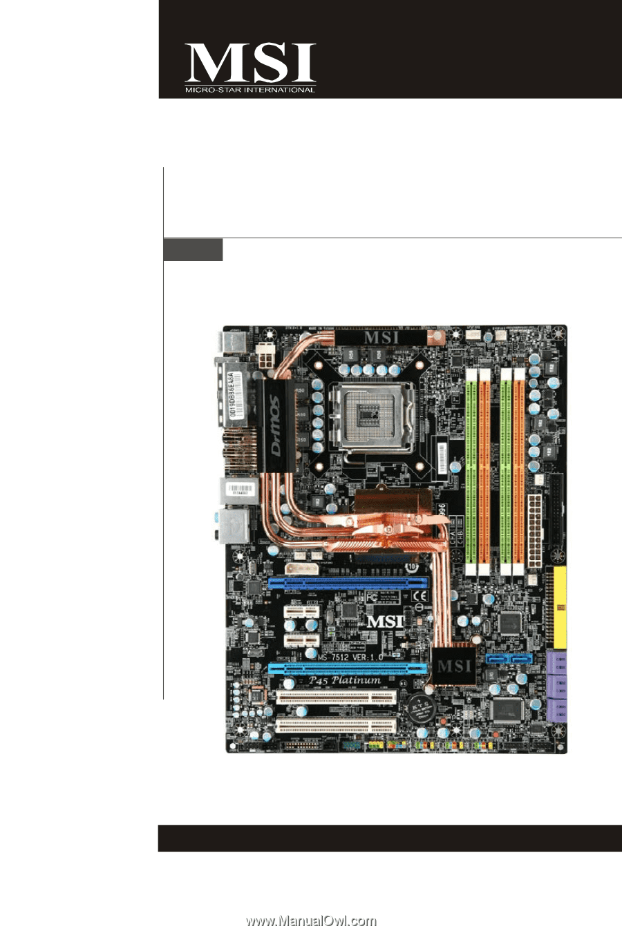
P45 Platinum Series
MS-7512 (v1.X) Mainboard
G52-75121X1