MSI P35 NEO2-FR User Guide - Page 23
Power Supply
 |
UPC - 816909039979
View all MSI P35 NEO2-FR manuals
Add to My Manuals
Save this manual to your list of manuals |
Page 23 highlights
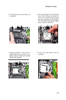
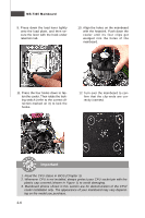
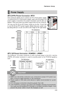
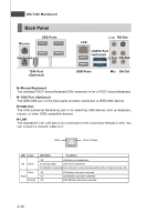
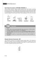
Hardware Setup Power Supply ATX 24-Pin Power Connector: ATX1 This connector allows you to connect an ATX 24-pin power supply. To connect the ATX 24-pin power supply, make sure the plug of the power supply is inserted in the proper orientation and the pins are aligned. Then push down the power supply firmly into the connector. You may use the 20-pin ATX power supply as you like. If you'd like to use the 20-pin ATX power supply, please plug your power supply along with pin 1 & pin 13 (refer to the image at the right hand). 13 ATX1 24 Pin Definition 1 PIN SIGNAL PIN SIGNAL 1 +3.3V 13 +3.3V 2 +3.3V 14 -12V 3 GND 15 GND 4 +5V 16 PS-ON# 5 GND 17 GND 6 +5V 18 GND 7 GND 19 GND 8 PW R OK 20 Res 9 5VSB 21 +5V 10 +12V 12 11 +12V 22 +5V 23 +5V 12 +3.3V 24 GND pin 13 pin 12 ATX 12V Power Connector: POWER1 / JPWR1 The POW ER1 12V power connector is used to provide power to the CPU. And the JPW R1 12V power connector is used to provide power to the PCIEX16 graphics card. 5 Pin Definition 1 PIN SIGNAL PIN SIGNAL Pin Definition 1 PIN SIGNAL 8 4 POWER1 1 GND 2 GND 3 GND 4 GND 5 +12V 6 +12V 7 +12V 8 +12V 1 2 JPWR1 3 4 5V GND GND 12V Important 1. Make sure that all the connectors are connected to proper ATX power supplies to ensure stable operation of the mainboard. 2. Power supply of 350 watts (and above) is highly recommended for system stability. 3. ATX 12V power connection should be greater than 18A. 4. If the POWER1 connector too closes the heatpipe and plug inconveniently. You could use the bundled ATX Extender to increase connector height. It can prevent the power cable to touch the heatpipe as well. 2-9
-
 1
1 -
2
-
3
-
4
-
5
-
6
-
7
-
8
-
9
-
10
-
11
-
12
-
13
-
14
-
15
-
16
-
17
-
 18
18 -
 19
19 -
 20
20 -
 21
21 -
 22
22 -
 23
23 -
 24
24 -
 25
25 -
 26
26 -
 27
27 -
 28
28 -
29
-
30
-
31
-
32
-
33
-
34
-
35
-
36
-
37
-
38
-
39
-
40
-
41
-
42
-
43
-
44
-
45
-
46
-
47
-
48
-
49
-
50
-
51
-
52
-
53
-
54
-
55
-
56
-
57
-
58
-
59
-
60
-
61
-
62
-
63
-
64
-
65
-
66
-
67
-
68
-
69
-
70
-
71
-
72
-
73
-
74
-
75
-
76
-
77
-
78
-
79
-
80
-
81
-
82
-
83
-
84
-
85
-
86
-
87
-
88
-
89
-
90
-
91
-
92
-
93
-
94
-
95
-
96
-
97
-
98
-
99
-
100
-
101
-
102
-
103
-
104
-
105
-
106
-
107
-
108
-
109
-
110
-
111
-
112
 |
 |