MSI P45 NEO-F User Guide
MSI P45 NEO-F - Motherboard - ATX Manual
 |
UPC - 816909045666
View all MSI P45 NEO-F manuals
Add to My Manuals
Save this manual to your list of manuals |
MSI P45 NEO-F manual content summary:
- MSI P45 NEO-F | User Guide - Page 1
P45 Neo/ G45 Neo / P43 Neo Series MS-7519 (v1.X) Mainboard G52-75191X1 i - MSI P45 NEO-F | User Guide - Page 2
's manual, please contact your place of purchase or local distributor. Alternatively, please try the following help resources for further guidance. Visit the MSI website for FAQ, technical guide, BIOS updates, driver updates, and other information: http://global.msi.com.tw/index.php? func=service - MSI P45 NEO-F | User Guide - Page 3
instructions carefully. 2. Keep this User's Manual for future reference. 3. Keep this equipment away from humidity. 4. Lay this equipment on a reliable flat surface before setting it up. 5. The openings on the enclosure arises, get the equipment checked by service personnel: † The power cord or plug - MSI P45 NEO-F | User Guide - Page 4
if not installed and used in accordance with the instructions, may cause harmful interference to radio communications. However, limits. VOIR LANOTICE D'INSTALLATIONAVANT DE RACCORDER AU RESEAU. Micro-Star International MS-7519 This device complies with Part 15 of the FCC Rules. Operation is subject - MSI P45 NEO-F | User Guide - Page 5
WEEE (Waste Electrical and Electronic Equipment) Statement v - MSI P45 NEO-F | User Guide - Page 6
vi - MSI P45 NEO-F | User Guide - Page 7
vii - MSI P45 NEO-F | User Guide - Page 8
Standard CMOS Features 3-6 Advanced BIOS Features 3-9 Integrated Peripherals 3-13 Power Management Setup 3-15 H/W Monitor ...3-18 BIOS Setting Password 3-19 Cell Menu ...3-20 Load Fail-Safe/ Optimized Defaults 3-24 Appendix A Realtek ALC888 Audio A-1 Installing the Realtek HD Audio Driver - MSI P45 NEO-F | User Guide - Page 9
Appendix B Dual Core Center B-1 Activating Dual Core Center B-2 Main ...B-3 DOT (Dynamic OverClocking B-5 Clock ...B-6 Voltage ...B-7 FAN Speed ...B-8 Temperature ...B-9 User Profile ...B-10 ix - MSI P45 NEO-F | User Guide - Page 10
x - MSI P45 NEO-F | User Guide - Page 11
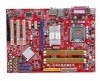
/ P43 Neo Series (MS-7519 v1.X) ATX mainboard. The P45 Neo/ G45 Neo/ P43 Neo Series mainboards are based on Intel® P45/ G45/ P43 & ICH10 chipsets for optimal system efficiency. Designed to fit the advanced Intel® Core 2 Extreme, Core 2 Quad, Core 2 Duo, Pentium Dual-Core and Celeron Dual-Core LGA775 - MSI P45 NEO-F | User Guide - Page 12
MS-7519 Mainboard Mainboard Specifications Processor Support - Intel® Core 2 Extreme, Core 2 Quad, Core 2 Duo, Pentium Dual- Core and Celeron Dual-Core processors in the LGA775 package - Intel® next generation 45 nm Multi-core CPU *(For the latest information about CPU, please visit ht t p: / / gl - MSI P45 NEO-F | User Guide - Page 13
intrusion connector - 1 SPDIF-out pinheader - 1 CD-in connector - 1 front audio pinheader - 1 TPM Module connector (optional) - 2 Hardware Overclock FSB jumpers (JB1 & JB2) TPM (optional) - Supports TPM Slots - 1 PCI Express x16 slot, supports up to PCI Express 2.0 x16 speed - 2 PCI Express x1 slots - MSI P45 NEO-F | User Guide - Page 14
3 PCI _E3 I/O Chip PCI 1 Intel ICH10 JMicron JMB368 SYSFAN2 SATA2 SATA4 ALC888 PCI 2 PCI 3 JMicron JMB381 (optional) JBAT1 BATT + JUSB4 JUSB3 JUSB2 JAUD1 JCD1 JSP1 FDD 1 JTPM1 (optional ) JFP2 JFP1 P45 Neo/ G45 Neo/ P43 Neo Series (MS-7519 v1.X) ATX Mainboard 1-4 SATA1 SATA3 JCI1 - MSI P45 NEO-F | User Guide - Page 15
Packing Checklist Getting Started MSI motherboard MSI Driver/Utility CD Back IO Shield Power Cable SATA Cable IDE Cable User's Guide and Quick Guide * The pictures are for reference only and may vary from the packing contents of the product you purchased. 1-5 - MSI P45 NEO-F | User Guide - Page 16
- MSI P45 NEO-F | User Guide - Page 17
Hardware Setup Chapter 2 Hardware Setup This chapter provides you with the information about hardware setup procedures. While doing the installation, be careful in holding the components and follow the installation procedures. For some components, if you install in the wrong orientation, the - MSI P45 NEO-F | User Guide - Page 18
MS-7519 Mainboard Quick Components Guide JB1/JB2, p.2-19 CPU, p.2-3 JPWR2, p.2-9 CPUFAN1, p.2-14 SYSFAN1, p.2-14 DDR2 DIMMs, p.2-7 Back Panel, p.2-10 JPWR1, p.2-9 IDE1, p.2-12 PCIE, p.2-20 PCI, p.2-20 SYSFAN2, p.2-14 JCI1, p.2-14 SATA, p.2-13 JAUD1, p.2-17 - MSI P45 NEO-F | User Guide - Page 19
to enhance heat dissipation. Replacing the CPU While replacing the CPU, always turn off the ATX power supply or unplug the power supply's power cord from the grounded outlet first to ensure the safety of CPU. Overclocking This mainboard is designed to support overclocking. However, please make sure - MSI P45 NEO-F | User Guide - Page 20
MS-7519 Mainboard CPU & Cooler Installation W hen you are installing the CPU, make sure the CPU has a cooler attached on the top to prevent overheating. Meanwhile, do not forget to apply some thermal paste on CPU before installing the heat sink/cooler fan for better heat dispersion. Follow the - MSI P45 NEO-F | User Guide - Page 21
Lift the load lever up and open the load plate. Hardware Setup 6. After confirming the CPU direction for correct mating, put down the CPU in the socket housing frame. Be sure to grasp on the edge of the CPU base. Note that the alignment keys are matched. alignment key 7. Visually inspect if the - MSI P45 NEO-F | User Guide - Page 22
MS-7519 Mainboard 9. Press down the load lever lightly onto the load plate, and then secure the lever correctly inserted. locking switch Important 1. Read the CPU status in BIOS (Chapter 3). 2. Whenever CPU is not installed, always protect your CPU socket pin with the plastic cap covered (shown in - MSI P45 NEO-F | User Guide - Page 23
modules. For more information on compatible components, please visit http://global.msi.com. tw/index.php?func=testreport DDR2 240-pin, 1.8V 56x2 - DDR2 memory modules are not interchangeable with DDR and the DDR2 standard is not backwards compatible. You should always install DDR2 memory modules in - MSI P45 NEO-F | User Guide - Page 24
MS-7519 Mainboard Installing Memory Modules 1. The memory module has only one notch on the center and the golden finger if the memory module is properly inserted in the DIMM slot. 3. Manually check if the memory module has been locked in place by the DIMM slot clips at the sides. Volt Notch - MSI P45 NEO-F | User Guide - Page 25
Res 9 5VSB 21 +5V 10 +12V 22 +5V 13 11 +12V 12 +3.3V 23 +5V 24 GND ATX 4-pin Power Connector: JPWR2 This power connector is used to provide power to the CPU. JPWR2 4 2 3 1 Pin Definition PIN SIGNAL 1 GND 2 GND 3 12V 4 12V pin 13 pin 12 Important 1. Make sure that - MSI P45 NEO-F | User Guide - Page 26
MS-7519 Mainboard Back Panel Mouse Parallel Port (optional) 1394 Port LAN Line-In RS-Out Line-Out CS-Out Keyboard Serial Port VGA Port (for G45) USB Port USB Port Mic SS-Out M ouse/K ey boar d The standard A parallel port is a standard printer port that supports Enhanced Parallel Port (EPP) - MSI P45 NEO-F | User Guide - Page 27
. Off 10 Mbit/sec data rate is selected. On 100 Mbit/sec data rate is selected. On 1000 Mbit/sec data rate is selected. Audio Ports These audio connectors are used for audio devices. It is easy to differentiate between audio effects according to the color of audio jacks. Line-In (Blue) - Line - MSI P45 NEO-F | User Guide - Page 28
MS-7519 Mainboard Connectors Floppy Disk Drive Connector: FDD1 This connector supports 360KB, 720KB, 1.2MB, 1.44MB or 2.88MB floppy disk drive. IDE Connector: IDE1 This connector supports IDE hard disk drives, to IDE device's documentation supplied by the vendors for jumper setting instructions. 2-12 - MSI P45 NEO-F | User Guide - Page 29
Hardware Setup Serial ATA Connector: SATA1~6 This connector is a high-speed Serial ATA interface port. Each connector can connect to one Serial ATA device. SATA1 SATA3 SATA5 SATA2 SATA4 SATA6 Important Please do not fold the Serial ATA cable into 90-degree angle. Otherwise, data loss may occur - MSI P45 NEO-F | User Guide - Page 30
MS-7519 Mainboard Fan Power Connectors: CPUFAN1, SYSFAN1, SYSFAN2 The fan power connectors support must use a specially designed fan with speed sensor to take advantage of the CPU fan control. CONTROL SE NS OR +1 2V GND GND +1 2V SENSOR/ BIOS utility and clear the record. CINTRU 1 GND 2 JCI1 2-14 - MSI P45 NEO-F | User Guide - Page 31
TPBCable power Ground IEEE1394 Bracket (optional) S/PDIF-Out Connector: JSP1 This connector is used to connect S/PDIF (Sony & Philips Digital Interconnect Format) interface for digital audio transmission. JSP1 VCC GND SPDIF S/PDIF Bracket (optional) 2-15 - MSI P45 NEO-F | User Guide - Page 32
MS-7519 Mainboard Front Panel Connectors: JFP1, JFP2 These connectors are for electrical connection to the front panel switches and LEDs. The JFP1 is compliant with Intel® Front Panel I/O Connectivity Design Guide : JCD1 This connector is provided for external audio input. JCD1 R GND L 2-16 - MSI P45 NEO-F | User Guide - Page 33
the front panel audio and is compliant with Intel® Front Panel I/O Connectivity Design Guide. JAUD1 9 1 10 2 HD Audio Pin Definition PIN SIGNAL Platform Module) module (optional). Please refer to the TPM security platform manual for more details and usages. 2 14 1 13 JTPM 1 Pin Signal - MSI P45 NEO-F | User Guide - Page 34
MS-7519 Mainboard Front USB Connector: JUSB1~4 These connectors, compliant with Intel® I/O Connectivity Design Guide, is ideal for connecting high-speed USB interface peripherals such as USB HDD, digital cameras, MP3 players, printers, modems and the like. 10 9 2 1 JUSB1~4 Pin - MSI P45 NEO-F | User Guide - Page 35
clearing the CMOS while the system is on; it will damage the mainboard. Hardware Overclock FSB Jumpers: JB1, JB2 You can overclock the FSB to increase the processor frequency by changing the jumpers JB1 and JB2. Follow the instructions below to set the FSB. JB2 1 JB1 1 3 JB2 JB1 Default - MSI P45 NEO-F | User Guide - Page 36
MS-7519 Mainboard Slots PCI (Peripheral Component Interconnect) Express Slot The PCI Express slot supports the PCI Express interface expansion card. The PCI Express 2.0x 16 supports up to 8.0 GB/s transfer rate. The PCI Express x 1 supports up to 250 MB/s transfer rate or BIOS configuration. 2-20 - MSI P45 NEO-F | User Guide - Page 37
Hardware Setup PCI Interrupt Request Routing The IRQ, acronym of interrupt request line and pronounced I-R-Q, are hardware lines over which devices can send interrupt signals to the microprocessor. The PCI IRQ pins are typically connected to the PCI bus pins as follows: PCI Slot 1 PCI Slot 2 PCI - MSI P45 NEO-F | User Guide - Page 38
x - MSI P45 NEO-F | User Guide - Page 39
This chapter provides information on the BIOS Setup program and allows you to configure the system for optimum use. You may need to run the Setup program when: ² An error message appears - MSI P45 NEO-F | User Guide - Page 40
digit refers to BIOS maker as A = AMI, W = AWARD, and P = PHOENIX. 2nd - 5th digit refers to the model number. 6th digit refers to the chipset as I = Intel, N = nVidia, and V = VIA. 7th - 8th digit refers to the customer as MS = all standard customers. V1.0 refers to the BIOS version. 040108 refers - MSI P45 NEO-F | User Guide - Page 41
BIOS Setup Control Keys Enter> Move to the sub-menu. If you want to return to the main menu, just press the . General Help The BIOS setup program provides a General Help screen. You can call up this screen from any menu by simply pressing . The - MSI P45 NEO-F | User Guide - Page 42
MS-7519 Mainboard The Main Menu Standard CMOS Features Use this menu for basic system configurations, such as time, date etc. Advanced BIOS BIOS Setting Password Use this menu to set the password for BIOS. Cell Menu Use this menu to specify your settings for frequency/voltage control and overclocking - MSI P45 NEO-F | User Guide - Page 43
BIOS Setup Load Optimized Defaults Use this menu to load the default values set by the mainboard manufacturer specifically for optimal performance of the mainboard. Save & Exit Setup Save changes to CMOS and exit setup. Exit Without Saving Abandon all changes and exit setup. 3-5 - MSI P45 NEO-F | User Guide - Page 44
MS-7519 Mainboard Standard CMOS Features The items in Standard CMOS Features Menu includes some basic setup items. Use the is . day Day of the week, from Sun to Sat, determined by BIOS. Read-only. month The month from Jan. to Dec. date The date from 1 to 31 can be - MSI P45 NEO-F | User Guide - Page 45
BIOS Setup Device / Vendor / Size It will showing the device information that you connected to the SATA connector. LBA/Large M ode This allows you to enable or disable the LBA Mode. Setting to Auto enables LBA mode if the device supports it and the devices is not already formatted with LBA mode - MSI P45 NEO-F | User Guide - Page 46
MS-7519 Mainboard Halt On The setting determines whether the system will stop if an error is detected at boot. Information Press to enter the sub-menu, and the following screen appears. This sub-menu shows the CPU information, BIOS version and memory status of your system (read only). 3-8 - MSI P45 NEO-F | User Guide - Page 47
function. You should enable this function at all times. The only time when you need to disable it is when you want to update the BIOS. After updating the BIOS, you should immediately re-enable it to protect it against viruses. Full Screen Logo Display This item enables this system to show the - MSI P45 NEO-F | User Guide - Page 48
MS-7519 Mainboard IOAPIC Function This field is used to enable or disable the APIC (Advanced Programmable Interrupt Controller). Due to compliance with PC2001 design guide values. CPU Feature Press to enter the sub-menu and the following screen appears: Execute Bit Support Intel's Execute - MSI P45 NEO-F | User Guide - Page 49
Device The items allow you to set the first/ second boot device where BIOS attempts to load the disk operating system. Boot From Other Device Setting Enter> to enter the sub-menu and the following screen appears: TCG/TPM SUPPORT Setting the option to [Yes] enables TPM (Trusted Platform Module) to - MSI P45 NEO-F | User Guide - Page 50
MS-7519 Mainboard Intel Robson Configuration Press to enter the sub-menu and the following screen appears: Intel Robson This item is used to enable/ disable Intel Robson technology. Intel Robson technology is turbo memory technology that can let the users to enable operation system without - MSI P45 NEO-F | User Guide - Page 51
Peripherals BIOS Setup USB Controller This setting allows you to enable/disable the onboard USB controller. USB Device Legacy Support Select disable the Extra IDE controller. HD Audio Controller This setting is used to enable/disable the onboard audio controller. On-Chip ATA Devices Press - MSI P45 NEO-F | User Guide - Page 52
MS-7519 Mainboard PCI IDE BusMaster This item allows you to enable/ disable BIOS built-in parallel port on the on-board Super I/O chipset that provides Standard, ECP, and EPP features. It has the following options: [Disabled] [ port to support both the ECP and EPP modes simultaneously. 3-14 - MSI P45 NEO-F | User Guide - Page 53
functions described in this section are available only when your BIOS supports S3 sleep mode. ACPI Function This item is to S1 sleep mode is a low power state. In this state, no system context is lost (CPU or chipset) and hardware maintains all system context. [S3] The S3 sleep mode is a lower - MSI P45 NEO-F | User Guide - Page 54
MS-7519 Mainboard Power Button Function This feature sets the function of the power button Wake Up Event Setup Press and the following sub-menu appears. Wake Up Event By Setting to [BIOS] activates the following fields, and use the following fields to set the wake up events. Setting to [OS - MSI P45 NEO-F | User Guide - Page 55
BIOS Setup Resume By PCI-E Device W hen set to [Enabled], the feature allows your system to be awakened from the power saving modes through any event on PCIE device. Resume By RTC Alarm The field is used to enable or disable the feature of booting up the system on a scheduled time/date. 3-17 - MSI P45 NEO-F | User Guide - Page 56
MS-7519 Mainboard H/W Monitor Chassis Intrusion The field enables or disables the feature of keep it with in a specific range. You can enable a fan target value here. If the current CPU fan temperature reaches to the target value, the smart fan function will be activated. It provides several sections - MSI P45 NEO-F | User Guide - Page 57
BIOS Setup BIOS Setting Password W hen you select this function, a message as below will appear on the screen: Type the password, up to six characters in length, and - MSI P45 NEO-F | User Guide - Page 58
MS-7519 Mainboard Cell Menu Important Change these settings only if you are familiar with the chipset. Current CPU / DRAM Frequency These items show the current clocks of CPU and Memory speed. Read-only. D.O.T. Control D.O.T. (Dynamic Overclocking Technology) is an automatic overclocking function, - MSI P45 NEO-F | User Guide - Page 59
manually, you also need to disable the Dynamic OverClocking first. Intel EIST The Enhanced Intel SpeedStep technology allows you to set the performance level of the microprocessor whether the computer is running on battery or AC power. This field will appear after you installed the CPU which support - MSI P45 NEO-F | User Guide - Page 60
MS-7519 DIMM and PCI slots to minimize the electromagnetic interference (EMI). CPU Voltage (V) / DRAM Voltage (V) / NB Voltage (V) / curves. If you do not have any EMI problem, leave the setting at Disabled for optimal system stability you are overclocking because even a slight jitter can introduce a - MSI P45 NEO-F | User Guide - Page 61
BIOS Setup Important 1. If you do not have any EMI problem, leave the setting at [Disabled] for optimal system stability and local EMI regulation. 3. Remember to disable Spread Spectrum if you are overclocking because even a slight jitter can introduce a temporary boost in clock speed which may just - MSI P45 NEO-F | User Guide - Page 62
MS-7519 Mainboard Load Fail-Safe/ Optimized Defaults The two options on the main menu allow users to restore all of the BIOS settings to the default Fail-Safe or Optimized values. The Optimized Defaults are the default values set by the mainboard manufacturer specifically for optimal performance - MSI P45 NEO-F | User Guide - Page 63
Appendix A Realtek ALC888 Audio The Realtek ALC888 provides 10-channel DAC that simultaneously supports 7.1 sound playback and 2 channels of independent stereo sound output (multiple streaming) through the Front-Out-Left and Front-OutRight channels. - MSI P45 NEO-F | User Guide - Page 64
MS-7519 Mainboard Installing the Realtek HD Audio Driver You need to install the HD audio driver for Realtek ALC888 codec to function properly before you can get access to 2-, 4-, 6-, 8- channel or 7.1+2 channel audio operations. Follow the procedures described below to install the drivers for - MSI P45 NEO-F | User Guide - Page 65
Realtek ALC888 Audio 3. Click Next to install the Realtek High Definition Audio Driver. 4. Click Finish to restart the system. Click here Select this option Click here A-3 - MSI P45 NEO-F | User Guide - Page 66
MS-7519 Mainboard Software Configuration After installing the audio driver, you are able to use the 2-, 4-, 6- or 8- channel audio feature now. Click the audio icon from the system tray at the lower-right corner of the screen to activate the HD Audio Configuration. It is also available to enable the - MSI P45 NEO-F | User Guide - Page 67
down the arrow, several kinds of sound effect will be shown for selection. Realtek HD Audio Sound Manager also provides five popular settings "Stone Corridor", "Bathroom", "Sewer pipe", "Arena" and "Audio Corridor" for quick enjoyment. You may choose the provided sound effects, and the equalizer - MSI P45 NEO-F | User Guide - Page 68
MS-7519 Mainboard Equalizer Selection Equalizer frees users from default settings; users may create their owned preferred settings by utilizing this tool. 10 bands of equalizer, ranging - MSI P45 NEO-F | User Guide - Page 69
Frequently Used Equalizer Setting Realtek recognizes the needs that you might have. By leveraging our long experience at audio field, Realtek HD Audio Sound Manager provides you certain optimized equalizer settings that are frequently used for your quick enjoyment. [How to Use It] Other than the - MSI P45 NEO-F | User Guide - Page 70
MS-7519 Mainboard Mixer In the Mixer part, you may adjust the volumes of the rear and front panels individually. 1. Adjust Volume You can adjust the volume of the speakers that you plugged in front or rear panel by select the Realtek HD Audio rear output or Realtek HD Audio front output items. - MSI P45 NEO-F | User Guide - Page 71
will be played from the rear panel, which is the default setting. Then you must to select the Realtek HD Audio front output from the scroll list first, and use a different program to play the second audio source (for example: use Winamp to play MP3 files). You will find that the second - MSI P45 NEO-F | User Guide - Page 72
MS-7519 Mainboard 3. Playback control Tool Mute Playback device This function is to let you freely decide which ports to output the sound. And this is essential when multistreamingplayback enabled. - Realtek HD Audio Rear Output - Realtek HD Audio Front Output Mute You may choose to mute single - MSI P45 NEO-F | User Guide - Page 73
Mute Recording device -Back Line in/Mic, Front Lin in -Realtek HD Audio Input Mute You may choose to mute single or multiple volume controls or to completely mute sound input. Tool - Show the following volume controls This - MSI P45 NEO-F | User Guide - Page 74
MS-7519 Mainboard Audio I/O In this tab, you can easily configure your multi-channel audio function and speakers. You can choose a desired multi-channel operation here. a. same as your device. - If not correct, Realtek HD Audio Manager will guide you to plug the device into the correct jack. A-12 - MSI P45 NEO-F | User Guide - Page 75
Connector Settings Click to access connector settings. Realtek ALC888 Audio Disable front panel jack detection (option) Find no function on front panel jacks? Please check if front jacks on your system are so-called AC' - MSI P45 NEO-F | User Guide - Page 76
MS-7519 Mainboard S/PDIF Short for Sony/Philips Digital Interface, a standard audio file transfer format. S/PDIF allows the transfer of digital audio signals from one device to another without having to be converted first to an analog format. Maintaining the viability of a digital signal prevents - MSI P45 NEO-F | User Guide - Page 77
Realtek ALC888 Audio Test Speakers You can select the speaker by clicking it to test its functionality. The one you select will light up and make testing sound. If any speaker fails to make sound, then check whether the cable is inserted firmly to the connector or replace - MSI P45 NEO-F | User Guide - Page 78
MS-7519 Mainboard Microphone In this tab you may set the function of the microphone. Select the Noise Suppression to remove the possible noise during recording, or - MSI P45 NEO-F | User Guide - Page 79
Realtek ALC888 Audio 3D Audio Demo In this tab you may adjust your 3D positional audio before playing 3D audio applications like gaming. You may also select different environment to choose the most suitable environment you like. A-17 - MSI P45 NEO-F | User Guide - Page 80
MS-7519 Mainboard Information In this tab it provides some information about this HD Audio Configuration utility, including Audio Driver Version, DirectX Version, Audio Controller & Audio Codec. You may also select the language of this utility by choosing from the Language list. Also there is a - MSI P45 NEO-F | User Guide - Page 81
Hardware Setup Connecting the Speakers W hen you have set the Multi-Channel Audio Function mode properly in the software utility, connect your speakers to the correct phone jacks in accordance with the setting in software utility. n 2-Channel Mode - MSI P45 NEO-F | User Guide - Page 82
MS-7519 Mainboard n 4-Channel Mode for 4-Speaker Output 1 4 2 5 3 6 1 Line In 2 Line Out (Front channels) 3 MIC 4 Line Out (Rear channels) 5 No function 6 No function A-20 - MSI P45 NEO-F | User Guide - Page 83
Realtek ALC888 Audio n 6-Channel Mode for 6-Speaker Output 1 4 2 5 3 6 1 Line In 2 Line Out (Front channels) 3 MIC 4 Line Out (Rear channels) 5 Line Out (Center and Subwoofer channel) 6 No function A-21 - MSI P45 NEO-F | User Guide - Page 84
MS-7519 Mainboard n 8-Channel Mode for 8-Speaker Output 1 4 2 5 3 6 1 Line In 2 Line Out (Front channels) 3 MIC 4 Line Out (Rear channels) 5 Line Out (Center and Subwoofer channel) 6 Line Out (Side channels) Important To enable 7.1 channel audio-out function on Vista operating system, you have - MSI P45 NEO-F | User Guide - Page 85
monitor or configure the hardware status of MSI Mainboard & MSI Graphics card in windows, such as CPU/GPU clock, voltage, fan speed and system has meet the following requirements: 1. Intel Pentium4 / Celeron, AMD Athlon XP/ Sempron or compatible CPU with PCI Express slot. 2. 256MB system - MSI P45 NEO-F | User Guide - Page 86
MS-7519 Mainboard Activating Dual Core Center Once you have your Dual Core Center installed (locate the setup source file in the setup CD accompanying with your mainboard, path: Utility --> MSI Utility --> Dual Core Center), it will have an icon in the system tray, a short cut icon on the - MSI P45 NEO-F | User Guide - Page 87
the MSI V044 (V044 has to install with the version 8.26 or newer driver)/ V046 MSI mainboard would be available. Introduction: Click each button appearing above to enter sub-menu to make further configuration or to execute the function. MB Click MB button to read current CPU temperature, FSB and CPU - MSI P45 NEO-F | User Guide - Page 88
MS-7519 Mainboard AV/ Game/ Office/ Silence/ Cool MSI provides five common settings for different environments. , you can adjust and monitor the fan speeds of MB and graphics card. Temperature In this sub-menu, you can monitor the temperatures of MB and graphics card. User Profile In this sub-menu, - MSI P45 NEO-F | User Guide - Page 89
the DOT function. DOT FSB-UP Rate button DOT FSB-DOWN Rate button Important Even though the Dynamic Overclocking Technology is more stable than manual overclocking, basically, it is still risky. We suggest user to make sure that your CPU can afford to overclock regularly first. If you find the - MSI P45 NEO-F | User Guide - Page 90
MS-7519 Mainboard Clock In the Clock sub-menu, you can see clock status (including FSB/ CPU clock of mainboard and GPU/ memory clock of graphics card) of your system. And you can select desired value for overclocking. There will be several items for you to select for overclocking after you - MSI P45 NEO-F | User Guide - Page 91
see voltage status (including Vcore, memory, GPU I voltage... etc.) of your system, and you can select desired value for overclocking. It will show several items to select for overclocking after you click the button. You can click the plus sign button to increase the voltage, or click the minus - MSI P45 NEO-F | User Guide - Page 92
MS-7519 Mainboard FAN Speed In the FAN Speed sub-menu, you can read fan with red color will be shown. Important 1. When you set the fan speed manually, please make sure to disabled the "CPU Smart FAN Target" item in the BIOS. 2. In the user profile, clicking the Save button can save the changes to - MSI P45 NEO-F | User Guide - Page 93
Dual Core Center Temperature In the Temperature sub-menu, you can see temperature status of your system. On the underside, it shows the graphs of the temperatures. Only the curves of the item which the button is lit up with red color will be shown. B-9 - MSI P45 NEO-F | User Guide - Page 94
MS-7519 Mainboard User Profile In the User Profile sub-menu, click the setting button that besides the user profile bar, and the next screen will appear. - MSI P45 NEO-F | User Guide - Page 95
Dual Core Center Use the draw bar to set the max system temperature. W hen the system temperature exceeds the threshold you defined, the system will pop up a warning message and shut down the system. Use the draw bar to set the minimal fan speed. When the fan speed is lower than the threshold you
-
 1
1 -
 2
2 -
 3
3 -
 4
4 -
 5
5 -
 6
6 -
 7
7 -
8
-
9
-
10
-
11
-
12
-
13
-
14
-
15
-
16
-
17
-
18
-
19
-
20
-
21
-
22
-
23
-
24
-
25
-
26
-
27
-
28
-
29
-
30
-
31
-
32
-
33
-
34
-
35
-
36
-
37
-
38
-
39
-
40
-
41
-
42
-
43
-
44
-
45
-
46
-
47
-
48
-
49
-
50
-
51
-
52
-
53
-
54
-
55
-
56
-
57
-
58
-
59
-
60
-
61
-
62
-
63
-
64
-
65
-
66
-
67
-
68
-
69
-
70
-
71
-
72
-
73
-
74
-
75
-
76
-
77
-
78
-
79
-
80
-
81
-
82
-
83
-
84
-
85
-
86
-
87
-
88
-
89
-
90
-
91
-
92
-
93
-
94
-
95
 |
 |
P45 Neo/ G45 Neo
/ P43 Neo Series
MS-7519 (v1.X) Mainboard
G52-75191X1