MSI P45 NEO-F User Guide - Page 33
Front Panel Audio Connector: JAUD1, TPM Module Connector: JTPM1 optinoal - manual
 |
UPC - 816909045666
View all MSI P45 NEO-F manuals
Add to My Manuals
Save this manual to your list of manuals |
Page 33 highlights
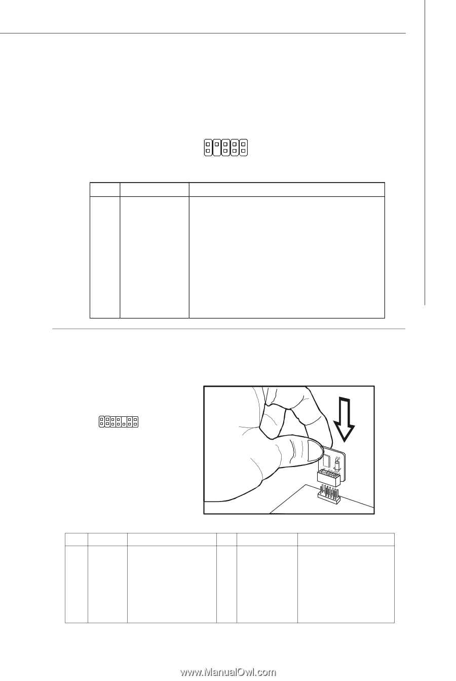
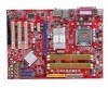
Hardware Setup Front Panel Audio Connector: JAUD1 This connector allows you to connect the front panel audio and is compliant with Intel® Front Panel I/O Connectivity Design Guide. JAUD1 9 1 10 2 HD Audio Pin Definition PIN SIGNAL DESCRIPTION 1 MIC_L 2 GND 3 MIC_R 4 NC 5 LINE out_R 6 MIC_JD 7 Front_JD 8 NC 9 LINE out_L 10 LINEout_JD Microphone - Left channel Ground Microphone - Right channel Analog Port - Right channel Jack detection return from front panel microphone JACK1 Jack detection sense line from the High Definition Audio CODEC jack detection resistor network No control Analog Port - Left channel Jack detection return from front panel JACK2 TPM Module Connector: JTPM1 (optinoal) This connector connects to a TPM (Trusted Platform Module) module (optional). Please refer to the TPM security platform manual for more details and usages. 2 14 1 13 JTPM 1 Pin Signal Description 1 LCLK LPC clock 3 LRST# LPC reset 5 LAD0 LPC address & data pin0 7 LAD1 LPC address & data pin1 9 LAD2 LPC address & data pin2 11 LAD3 LPC address & data pin3 13 LFRAME# LPCFrame Pin Signal 2 3V_STB 4 VCC3 6 SIRQ 8 VCC5 10 KEY 12 GND 14 GND Description 3V standby power 3.3V power Serial IRQ 5V power No pin Ground Ground 2-17
-
 1
1 -
2
-
3
-
4
-
5
-
6
-
7
-
8
-
9
-
10
-
11
-
12
-
13
-
14
-
15
-
16
-
17
-
18
-
19
-
20
-
21
-
22
-
23
-
24
-
25
-
26
-
27
-
 28
28 -
 29
29 -
 30
30 -
 31
31 -
 32
32 -
 33
33 -
 34
34 -
 35
35 -
 36
36 -
 37
37 -
 38
38 -
39
-
40
-
41
-
42
-
43
-
44
-
45
-
46
-
47
-
48
-
49
-
50
-
51
-
52
-
53
-
54
-
55
-
56
-
57
-
58
-
59
-
60
-
61
-
62
-
63
-
64
-
65
-
66
-
67
-
68
-
69
-
70
-
71
-
72
-
73
-
74
-
75
-
76
-
77
-
78
-
79
-
80
-
81
-
82
-
83
-
84
-
85
-
86
-
87
-
88
-
89
-
90
-
91
-
92
-
93
-
94
-
95
 |
 |