MSI P965 NEO-F User Guide - Page 31
CD-In Connector: CD_IN1, Front Panel Audio Connector: JAUD1, SPDIF-Out Connector: JSPD1 2pin / 3pin
 |
UPC - 816909035490
View all MSI P965 NEO-F manuals
Add to My Manuals
Save this manual to your list of manuals |
Page 31 highlights
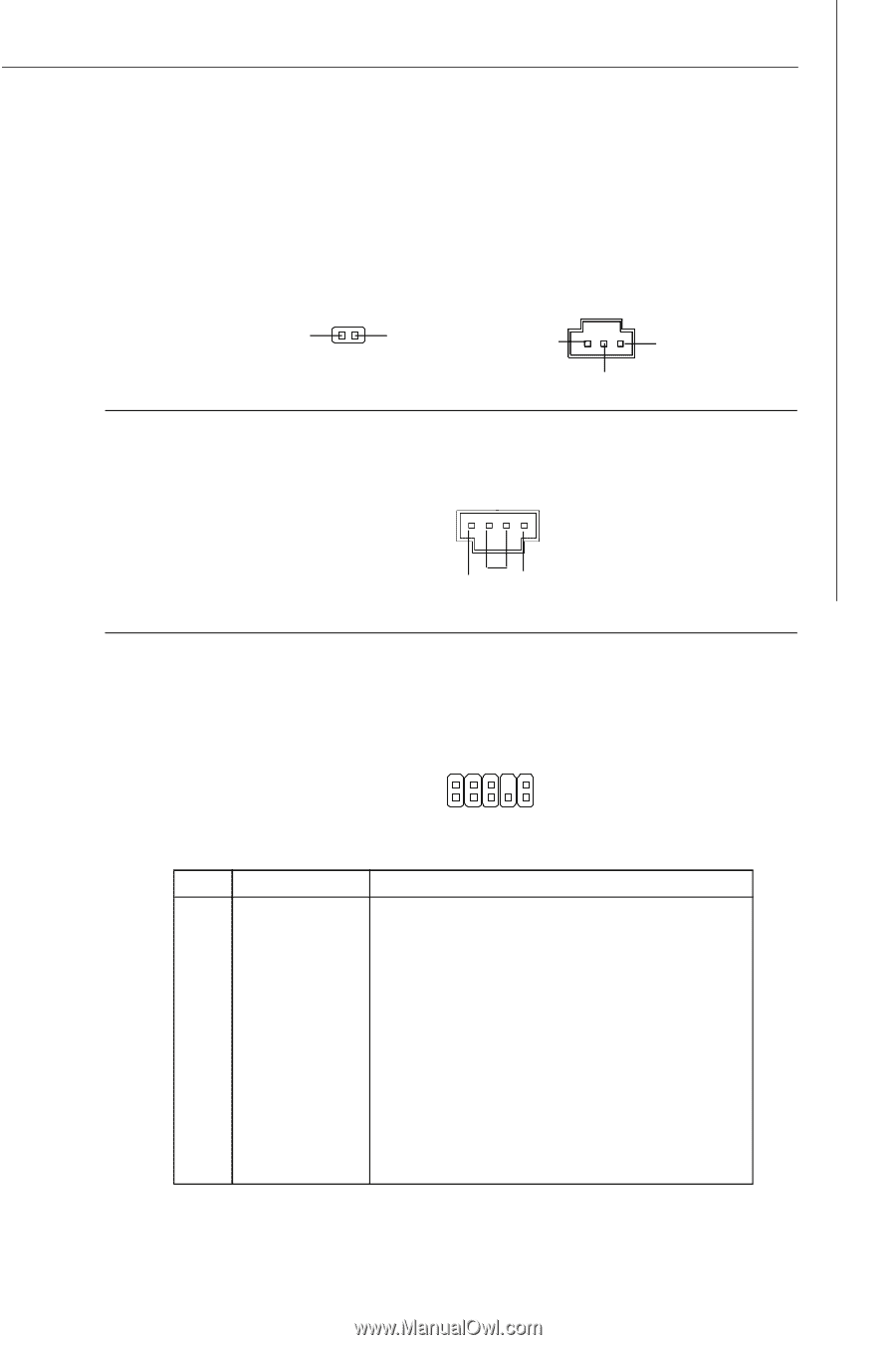
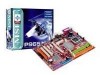
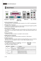
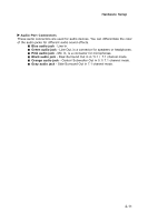
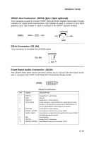
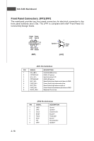
Hardware Setup SPDIF-Out Connector: JSPD1 (2pin / 3pin optional) This connector is used to connect SPDIF (Sony & Philips Digital Interconnect Format) interface for digital audio transmission. 2pin header is used to connect to the HDMI graphics card. 3pin header is used to connect to the SPDIF optional bracket. JSPD1 SPDF0 GND (optional) VCC GND SPDIF CD-In Connector: CD_IN1 This connector is provided for CD-ROM audio. CD_IN1 L GND R Front Panel Audio Connector: JAUD1 The JAUD1 front panel audio connector allows you to connect the front panel audio and is compliant with Intel® Front Panel I/O Connectivity Design Guide. JAUD1 2 1 10 9 JAUD1 Pin Definition PIN SIGNAL DESCRIPTION 1 PORT 1L Analog Port 1 - Left channel 2 GND Ground 3 PORT 1R Analog Port 1 - Right channel 4 PRESENCE# Active low signal - signals BIOS that a High Definition Audio dongle is connected to the analog header. PRESENCE# = 0 when a High Definition Audio dongle is connected. 5 PORT 2R Analog Port 2 - Right channel 6 SENSE1_RETIRN Jack detection return from front panel JACK1 7 SENSE_SEND Jack detection sense line from the High Definition Audio CODEC jack detection resistor network 8 KEY Connector Key 9 PORT 2L Analog Port 2 - Left channel 10 SENSE2_RETIRN Jack detection return from front panel JACK2 2-15
-
 1
1 -
2
-
3
-
4
-
5
-
6
-
7
-
8
-
9
-
10
-
11
-
12
-
13
-
14
-
15
-
16
-
17
-
18
-
19
-
20
-
21
-
22
-
23
-
24
-
25
-
 26
26 -
 27
27 -
 28
28 -
 29
29 -
 30
30 -
 31
31 -
 32
32 -
 33
33 -
 34
34 -
 35
35 -
 36
36 -
37
-
38
-
39
-
40
-
41
-
42
-
43
-
44
-
45
-
46
-
47
-
48
-
49
-
50
-
51
-
52
-
53
-
54
-
55
-
56
-
57
-
58
-
59
-
60
-
61
-
62
-
63
-
64
-
65
-
66
-
67
-
68
-
69
-
70
-
71
-
72
-
73
-
74
-
75
-
76
-
77
-
78
-
79
-
80
-
81
-
82
-
83
 |
 |