Mackie 1604-VLZ Pro Specifications - Page 7
Architect & Engineering Specifications - 16 channel mixer
 |
View all Mackie 1604-VLZ Pro manuals
Add to My Manuals
Save this manual to your list of manuals |
Page 7 highlights
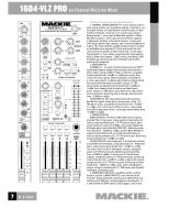
TRIM 1 U M-I1C0dGBAVIN 0 60 +15dB -45dB AUX U 1 +15 U OO OO OO OO 2 +15 PRE U 3 5 +15 U 4 6 +15 5/6 SHIFT EQ U HI 12k -15 +15 U MID -15 +15 800 200 2k 100 8k U LOW 80Hz -15 +15 LOW CUT 75 Hz 18dB/OCT PAN LR 1 MUTE OL -20 SOLO 1-2 3-4 L - R OO 1604-VLZ PRO 12V 16-CHANNEL MIC/ LINE MIXER 0.5A WITH PREMIUM XDRTM MIC PREAMPLIFIERS LAMP U U U 1 +10 U 1 +20 U 1 TO AUX SEND 1 +15 EFFECTS TO U MONITORS OO OO OO OO OO OO 2 +10 AUX SEND 2 +20 U 2 TO AUX SEND 2 +15 ASSIGN OPTIONS 1 3 OO OO SOLO 2 +20 U MAIN MIX 1-2 TO SUBS 3-4 SOLO 4 PHAN PWR C-R / PHNS RETURNS +20 ONLY SOLO STEREO AUX RETURN OO MAX CTL ROOM / PHONES TAPE SUBS 1-2 SUBS 3-4 MAIN MIX CTL ROOM SOURCE U LEFT RIGHT 0 dB=0 dBu 28 OO +20 10 TAPE IN 7 4 TAPE TO 2 MAIN MIX 0 2 OO 4 MAX SOLO LEVEL SET 7 10 MODE NORMAL (AFL) LEVEL SET (PFL) 20 30 RUDE SOLO LIGHT ASSIGN TO MAIN MIX LEFT RIGHT 1 LEFT RIGHT 2 LEFT RIGHT 3 LEFT RIGHT 4 dB 10 PHONES MAIN MIX dB 10 5 5 U U 5 5 10 10 20 20 30 30 40 40 50 50 60 60 OO OO Architect & Engineering Specifications 1. GENERAL CONFIGURATION. The mixer shall accommodate 16 line and/or 16 microphone signals, channels 1-16; and shall include 16 Send/Return channel Inserts; 8 channel Direct Outputs, channels 1-8; 4 stereo pairs of Aux Return inputs; 1 stereo pair of Main Mix outputs; 1 Main Mix Mono output, 1 stereo pair of Control Room outputs; 4 Submaster outputs; 6 Aux Send outputs; 1 stereo pair of RCA-type phono Tape outputs; and 1 stereo Headphones output. The mixer shall be capable of placement on a table or installation in a standard 19-inch rack mount via rack rail brackets (included); shall be fitted with 1 rocker-type Power switch; 1 3-pin power receptacle with user-replaceable 5x20mm fuse drawer; 1 BNC socket, providing 12VDC for fitting an external lamp (not included); and shall be entirely self-contained. 2. MIXER INPUTS. CHANNELS 1-16: Each channel shall include an XDR™ (Extended Dynamic Range) electronically balanced microphone input, using an XLR-3-F-type connector, accepting nominal levels from -60dBu to +4dBu via a rotary Trim control. Phantom power shall be globally-controlled via a rocker-type switch. 16 Balanced/unbalanced (bal/unbal) line inputs shall be wired in parallel, using 1/4" TRS phone jacks, accepting nominal levels from -40dBu to +4dBu. Each channel shall include a pre-fader Insert point, using 1/4" TRS phone jacks (tip=send, ring=return, sleeve=ground), delivering and accepting nominal levels from -10dBV to +4dBu. OTHER INPUTS: The mixer shall include 8 bal/unbal Aux Return inputs, forming four stereo pairs, using 1/4" TRS phone jacks, accepting nominal levels from -10dBV to +4dBu; and 1 stereo pair of Tape In jacks, using unbalanced RCA-type phono jacks, accepting nominal levels from -10dBV to +4dBu. 3. MIXER OUTPUTS. MAIN OUTPUTS: The mixer's Main Mix stereo outputs shall be fitted in two ways: Using symmetrically balanced (also accepting unbalanced) 1/4" TRS phone jacks, delivering maximum output of +28dBu; and using unbalanced RCA-type phono jacks (labeled TAPE OUT), delivering nominal levels from -10dBV to +4dBu; and the Main Mix Mono output shall be fitted with one symmetrically balanced (also accepting unbalanced) 1/4" TRS phone jack, delivering nominal levels from -10dBV to +4dBu. OTHER OUTPUTS: Input channels 1-8 shall each include a post-fader Direct Output, using bal/unbal 1/4" TRS phone jacks, delivering nominal levels from -10dBV to +4dBu. The mixer shall include 4 Submaster outputs, using bal/ unbal 1/4" TRS phone jacks, delivering nominal levels from -10dBV to +4dBu; 1 stereo pair of Control Room outputs, using bal/unbal 1/4" TRS phone jacks, delivering nominal levels from -10dBV to +4dBu; 6 Aux Send outputs using bal/unbal 1/4" TRS phone jacks, delivering nominal levels from -10dBV to +4dBu; and 1 stereo Headphones output, using an unbalanced 1/4" TRS phone jack (tip=left, ring=right, sleeve=ground). 4. MIXER INPUT SECTION. In addition to the controls listed in section 2 (MIXER INPUTS), each channel shall include 4 rotary Aux Send controls and 1 Shift switch, providing up to 15dB gain, routing signals to Aux Sends 1, 2, 3 and 4 when the Shift switch is disengaged, and to Aux 7
-
 1
1 -
 2
2 -
 3
3 -
 4
4 -
 5
5 -
 6
6 -
 7
7 -
 8
8
 |
 |
