Mackie 1642-VLZ Pro Spec Sheet - Page 7
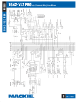
Architect & Engineering Specifications - 16 channel mixer
 |
View all Mackie 1642-VLZ Pro manuals
Add to My Manuals
Save this manual to your list of manuals |
Page 7 highlights
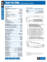
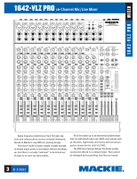
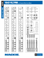
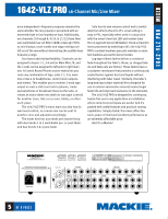
Architect & Engineering Specifications 1. GENERAL CONFIGURATION. The mixer shall consist of 8 mono channels accommodating line and/or microphone signals (Channels 1-8), two hybrid channels accomodating stereo line and/or mono microphone signals (Channels 9/10 & 11/12) and two stereo channels accomodating stereo line inputs (Channels 13/14 &15/16); and shall include 8 Send/ Return channel Inserts and 8 channel Direct Outputs, channels 1-8; 4 stereo pairs of Aux Return inputs; 2 stereo pairs of Main Mix outputs; 1 Main Mix Mono output with level control, 1 stereo pair of Control Room outputs; 4 Submaster outs double-bussed to 8 outputs; 4 Aux Send outputs; 2 stereo pairs of RCA-type Tape inputs and outputs; and 2 stereo Headphones outputs. The mixer shall be capable of placement on a table or installation in a standard 19-inch rack mount via RM1642-VLZ rack rail brackets (not included); shall be fitted with 1 rocker-type Power switch; 1 3-pin power receptacle with user-replaceable 5x20mm fuse drawer; 1 BNC socket, providing 12VDC for fitting an external lamp (not included); and shall be entirely self-contained. 2. MIXER INPUTS. CHANNELS 1-8: Each channel shall include an XDR™ (Extended Dynamic Range) electronically balanced microphone input, using an XLR-3-F-type connector, accepting nominal levels from -60dBu to +4dBu via a rotary Trim control. 48V phantom power shall be globally controlled via a rocker-type switch. Each channel shall also include a balanced/unbalanced (bal/unbal) line input wired in parallel, using 1/4" TRS phone jacks, accepting nominal levels from -45dBu to +4dBu. Each channel shall include a prefader Insert point, using 1/4" TRS phone jacks (tip=send, ring=return, sleeve=ground), delivering and accepting nominal levels from -10dBV to +4dBu. CHANNELS 9/10 & 11/12 (two channel strips): Each channel strip shall include an XDR™ (Extended Dynamic Range) electronically balanced microphone input, using an XLR-3-F-type connector, accepting nominal levels from -60dBu to +4dBu via a rotary Trim control. Phantom power shall be globallycontrolled via a rocker-type switch. Each channel strip shall also include a stereo pair of balanced/unbalanced (bal/unbal) line inputs wired in parallel, using 1/4" TRS phone jacks, accepting nominal levels from -45dBu to +4dBu. CHANNELS 13/14 & 15/16 (two channel strips): Each channel strip shall include a stereo pair of balanced/ unbalanced (bal/unbal) line inputs wired in parallel, using 1/4" TRS phone jacks, accepting nominal levels from -45dBu to +4dBu. OTHER INPUTS: The mixer shall include 8 bal/unbal Aux Return inputs, forming four stereo pairs, using 1/4" TRS phone jacks, accepting nominal levels from -10dBV to +4dBu; and 1 stereo pair of Tape In jacks, using unbalanced RCA-type phono jacks (labeled TAPE OUT), accepting nominal levels from -10dBV to +4dBu. 3. MIXER OUTPUTS. MAIN OUTPUTS: The mixer's Main Mix stereo outputs shall be fitted in three ways: Using balanced a stereo pair of XLR-3-M-type connectors, delivering maximum output of 28dBu, including 1 recessed Main Output Level switch to provide 30 dB of attenuation (XLR outputs only); using a stereo pair of symmetrically balanced (also accepting unbalanced) 1/4" TRS phone jacks, delivering nominal levels from -10dBV to +4dBu; and using a stereo pair of unbal- anced RCA-type phono jacks, delivering nominal levels from -10dBV to +4dBu; one stereo pair of 1/4" TRS pre-fader insert points delivering and accepting levels from +4dBu nominal to +22dBu max. The mixer's Main Mix Mono output shall be fitted with one symmetrically balanced (also accepting unbalanced) 1/4" TRS phone jack, delivering nominal levels from -10dBV to +4dBu. OTHER OUTPUTS: Input channels 1-8 shall each include a post-fader Direct Output, using bal/unbal 1/4" TRS phone jacks, delivering nominal levels from -10dBV to +4dBu. The mixer shall include 4 Submaster outs double-bused to 8 outputs, using bal/unbal 1/4" TRS phone jacks, delivering nominal levels from -10dBV to +4dBu; 1 stereo pair of Control Room outputs, using bal/unbal 1/4" TRS phone jacks, delivering nominal levels from -10dBV to +4dBu; 4 Aux Send outputs using bal/unbal 1/4" TRS phone jacks, delivering nominal levels from -10dBV to +4dBu; and 2 stereo Headphones outputs, using an unbalanced 1/4" TRS phone jack (tip=left, ring=right, sleeve=ground). 4A. MIXER INPUT SECTION-ALL CHANNELS. In addition to the controls listed in section 2 (MIXER INPUTS), each channel shall include 4 rotary Aux Send controls, providing up to 15dB gain; 1 pre/post switch for Auxes 1 and 2; 1 rotary Pan control, 4dB attenuation panned center; 1 Mute switch; 1 dual-mode solo switch (AFL or PFL, globally switched); 3 output Assign switches, delivering the channel's signal, relative to its Pan setting, to the Main L-R Mix, Submasters 1-2 and Submasters 3-4; and 1 channel Fader, providing up to 10dB above unity gain. Additionally, each channel shall include two LED indicators; a -20/Solo LED acting as a Signal Present indicator by flickering and as a channel Solo indicator by glowing steadily; and an OL/Mute LED, acting as an overload indicator by flickering and as a channel Mute indicator by glowing steadily. 4B. CHANNELS 1-8. In addition to the controls listed in Section 2 and 4A, each channel shall include 4 rotary equalization (EQ) controls: ±15dB fixed 12kHz shelving gain, ±15dB midrange peaking gain, 100Hz - 8kHz midrange frequency, ±15dB fixed 80Hz shelving control and an 18dB/octave 75Hz Low Cut filter accessible via push switch. 4C. CHANNELS 9-16. In addition to the controls listed in Section 2 and 4A, each channel shall include 4 rotary equalization (EQ) controls: ±15dB fixed 12kHz shelving gain, ±15dB fixed 3K High midrange peaking gain, ±15dB fixed 800HZ Low midrange peaking gain, and ±15dB fixed 80Hz shelving control. Channels 9/10 & 11/12 also include an 18dB/octave 75Hz Low Cut filter accessible via push switch. 5. MIXER OUTPUT SECTION. The mixer shall have 1 Main Mix stereo fader, providing up to 10dB gain; 4 Submaster mono faders, each providing up to 10dB gain; independent Left and Right assign switches for each Submaster; separate control room and phones rotary stereo level controls, providing up to 10dB gain; 1 Source Matrix, including 4 switches to deliver any combination of stereo signals to the Control Room, Phones and Meters, including Main Mix, Submasters 1-2, Submasters 3-4 and Tape, which shall be replaced by solo signals resulting from the engagement of any Solo switch; 1 rotary stereo Tape In level control, providing up to 20dB gain; 1 Tape to Main Mix switch; 1 Solo Mode switch to globally determine solo type (pre-fader listen or after-fader listen, in place); 1 rotary stereo Solo level control, providing up to 10dB gain; 4 rotary stereo Aux Return level controls, providing up to 20dB gain; 2 7
-
 1
1 -
 2
2 -
 3
3 -
 4
4 -
 5
5 -
 6
6 -
 7
7 -
 8
8
 |
 |
