Mackie 24.8Bus Architect's Specifications - Page 1
Mackie 24.8Bus Manual
 |
View all Mackie 24.8Bus manuals
Add to My Manuals
Save this manual to your list of manuals |
Page 1 highlights
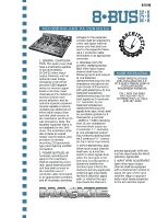
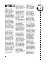
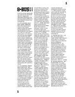
2/6/98 RECORDING AND PA CONSOLES 1. GENERAL CONFIGURATION. The audio mixer shall have a mainframe capable of accommodating 16/24/32 inline input/ output channels, with an optional meter bridge consisting of 16/24/32 precision LED bargraph meters to monitor signal levels in all inline input channels and VU meters to monitor control room source selection, and an optional separate expander console capable of accommodating an additional 24 inline input/output channels that shall connect to the mainframe via 37-pin Dsub connectors. Note: The separate expander frame is not available for the 16•8 mixer. The mainframe shall also include an overall master control section, and provision for directly mounting 12V gooseneck type panel lighting via BNC connectors. 2. POWER SUPPLIES. All necessary operating voltages for the mainframe shall be supplied by a tworack- space external power unit that shall connect to the mainfram via a 7conductor cable terminated in an appropriate connector, and all necessary operating voltages for the expander console shall be supplied by a two rack space external power unit that shall connect to the expander frame via a 7-conductor cable terminated in an appropriate connector. 3. CHANNEL INPUTS/ OUTPUT TERMINATIONS. Each inline input/output channel shall have the following inputs and outputs: a) one balanced transformerless input for lowimpedance microphone via 3-pin female XLR connector with gold-plated pins, b) one balanced/unbalanced transformerless input for linelevel signals via 3-conductor 1/4" connector, c) one balanced/unbalanced transformerless input for signals from tape, which shall be switchable globally for 8 channels for a nominal -10dBV or +4dBU operating level, d) one unbalanced line-level direct output via 2-conductor 1/4" connector, e) one unbalanced output/ input channel patching insert via 3-conductor 1/4" connector (tip = send, ring =return). 4. INPUT SWITCHING. Each inline input/output channel shall have: a) a mic/line switch to select signals from either the mic input or the line input, b) a flip switch to determine whether the mic/line input is fed to the channel's primary signal path while the tape input feeds the Mix-B (Monitor) signal path, or whether the tape input feeds the channel's MORE INFORMATION THESE SPECIFICATIONS ARE AVAILABLE ON 3.5" PC & MAC FORMAT DISK IN POPULAR WORD PROCESSOR FORMATS s CALL 800/258-6883 FAX 425/487-4337 OUTSIDE THE U.S., CALL 425/487-4333 primary signal path while the mic/line input feeds the Mix-B (Monitor) signal path. 5. INPUT LEVEL ADJUSTMENT. Each inline input/output channel shall be equipped with a channel trim control to adjust the gain of the input amplifier stage to appropriately match levels presented to the mic and line inputs. ®
-
 1
1 -
 2
2 -
 3
3 -
 4
4 -
 5
5
 |
 |