Mackie M1400/M1400i Spec Sheet - Page 7
Amplifier
 |
View all Mackie M1400/M1400i manuals
Add to My Manuals
Save this manual to your list of manuals |
Page 7 highlights
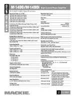
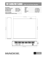
M•1400/M•1400i AMPLIFIER M•1400/M•1400i High-Current Power Amplifier (continued from page 6) selecting limiter on, limiter off, and subwoofer mode. The defeatable electronic limiter circuit shall sense the onset of clipping and shall limit the input signal and thereby prevent the output from clipping. The amplifier shall have a two-way switch appearing on the rear panel for selecting between a 63Hz and 125Hz low-pass cutoff frequency when subwoofer mode is selected. 11. LOW-CUT FILTER. Each channel shall have a lowcut filter with a variable frequency control appearing on the rear panel covering a range of 10Hz (OFF) to 170Hz. 12. CONSTANT DIRECTIVITY HORN EQ. Each channel shall have a two-way switch appearing on the rear panel for selecting a constant directivity horn equalization circuit. When selected, this circuit shall provide a 6 dB per octave high-frequency boost. The EQ shall have a variable frequency control appearing on the rear panel covering a range of 2kHz to 6kHz. The 6kHz position shall be called AIR. 13. PHYSICAL CONFIGURATION. The amplifier shall be rack-mountable with rear support rails for extra support, and shall have a steel chassis frame painted gray-black. The amplifier shall be 19" wide (483mm), 3.5" (2U) tall (89mm), and 15.25" deep (387mm), and shall weigh 36 pounds (16.3 kg). 14. DESIGNATION. The power amplifiers shall be a Mackie M•1400 and M1400i. 7 OF 8 PAGES
-
 1
1 -
 2
2 -
 3
3 -
 4
4 -
 5
5 -
 6
6 -
 7
7 -
 8
8
 |
 |