Mackie M1400/M1400i Contactor's Specs (M1400) - Page 3
V, 2V, and 3V. - hot
 |
View all Mackie M1400/M1400i manuals
Add to My Manuals
Save this manual to your list of manuals |
Page 3 highlights
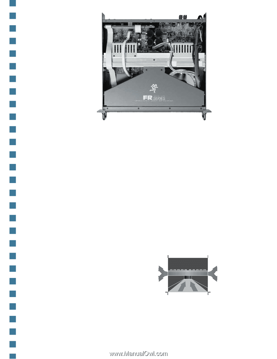
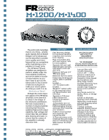
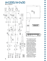
Each channel has an independent gain control with 40 detents for accurately setting and matching the gain between channels. The gain controls are calibrated in dB (from off to 30) and in volts (with indications of 1V, 2V, and 3V). Six discrete LEDs are used to indicate signal level for each channel, including a signal present LED, indicators at -20, -9, -6, and -3dB below full power, and an overload LED to indicate when the output has reached the clipping point. Outputs. The M•1200 and M•1400 differ in their output connector configurations. They both come with heavy-duty 5-way binding posts, which can accept standard double banana plugs, spade lugs, or bare wire (Export versions will not accept banana plugs due to European safety requirements). The M•1200 also has 1/4" TS phone jack outputs in parallel with the binding posts. The M•1400 comes with Neutrik brand Speakon® connectors in parallel with the binding posts. Stereo, Mono and Bridge modes. The amplifiers can be operated in one of three modes. In stereo mode, the amplifier operates with two inputs and two outputs. It accepts separate channel 1 and 2 input signals, and outputs separate channel 1 and 2 signals. In mono mode, the ampli- so it doesn't degrade the audio signal in any way. T-Design Constant Gradient Cooling Tunnel. Most amplifi- ers have a fan in the back that blows air (along with dust and other contami- nants) into the inside of the amplifier, across the heatsinks fier operates with one input and two identical outputs. It accepts an input signal through channel 1, and outputs the same signal at both channel 1 and 2 speaker outputs. In bridge mode, the amplifier operates with one input and one output. It accepts an input signal through channel 1, and combines the power of both output sections into a single output, using the channel 1 positive and channel 2 positive speaker output terminals. Clipping eliminator. as well as all the other internal components, and finally out through the front. These designs are cheap to implement, but not very efficient. Others use a cooling tunnel with the fan at one end. The problem with this design is that the heat from the first transistors warms the air so that by the time the air reaches the end of the tunnel it's too hot to provide sufficient cooling. Our T-Design Constant Gradient Cooling Tunnel offers a much more efficient Mackie Designs power method of providing cool amplifiers use a method of air to all the transistors with- protecting the amplifier and out blowing contaminants the speakers from clipping all over its insides. A dual- that doesn't affect the low speed fan is located in the impedance capablility of the center of the amplifier, direct- amplifier. A defeatable limiter ing air from the front of the circuit is em- amplifier ployed that through a reduces the large intake input signal manifold into when the out- the cooling put of the tunnel. The amplifier ap- cool air is proaches the clipping point. Cooling tunnel airflow evenly distributed The moment the output from the middle of the tun- level drops below clipping, nel to each end, where the the limiter turns off and is warm air then exits the effectively "out-of-circuit," amplifier on either side. 3
-
 1
1 -
 2
2 -
 3
3 -
 4
4 -
 5
5 -
 6
6
 |
 |