Mackie SR244 VLZ Pro / SR324 VLZ Pro SR24•4 Specifications - Page 7
Mixer
 |
View all Mackie SR244 VLZ Pro / SR324 VLZ Pro manuals
Add to My Manuals
Save this manual to your list of manuals |
Page 7 highlights
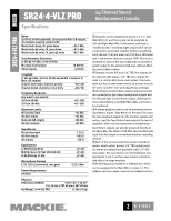
SR24•4-VLZ PRO MIXER SR24•4-VLZ PRO Architects' and Engineers' Specifications 1. GENERAL CONFIGURATION. The audio mixer shall have a free-standing frame fitted with four resilient feet suitable for tabletop placement. The frame shall be comprised of 20 monaural input channels, 2 stereo input channels, 4 submix output channels and 2 main output channels. The monaural input channels shall be capable of accepting either microphone- or line-level signals, and shall be fitted with trim, equalization, balance, and auxiliary send controls; solo, mute, and bus assign switches; level-indicating LEDs and insert jacks. The stereo input channels shall be capable of accepting either stereo or monaural line-level signals, and shall be fitted with stereo trim, equalization, balance, and auxiliary send controls; solo, mute and bus assign switches; and level indicating LEDs. The submix outputs shall each have level, pan, and "air" controls; solo and assign switches; and a bus access insert jack. The main outputs shall share a stereo master output fader and shall be fitted with insert jacks. Additionally, the mixer shall include a pre-fader/post fader solo function, a main monaural output with level control derived from the main stereo outputs, 6 monitor/effects send outputs, 4 stereo effects return inputs with switching and control functions, 1 stereo control room monitor output, 2 stereo headphone outputs, 1 set of stereo tape recorder convenience outputs, and 1 set of stereo tape monitor inputs. 2. POWER SUPPLY. All necessary operating voltages for the mixer shall be provided by an internal power supply. 3. INPUT CHANNEL CONNECTIONS. Each monaural channel (1-20) shall include an XDR™ (Extended Dynamic Range) electronically balanced microphone input, using an XLR-3-F-type connector, accepting nominal levels from -60 dBu to +4 dBu via a rotary Trim control. Phantom power shall be globally controlled via a rocker-type switch. Each monaural input channel shall also have an electronically balanced line level input, accommodating a nominal line level of between -10 dBV and +4 dBu, and appearing on the rear panel as a 1/4" TRS phone jack. Each stereo input channel shall have left and right electronically balanced line level input, accommodating a nominal line level of between -10 dBV and +4 dBu, and appearing on the rear panel as 1/4" TRS phone jacks. These jacks shall be fitted with internal switching contacts to accommodate monaural configuration. Additionally, each of the monaural input channels (1-20) shall offer an unbalanced insert connection, appearing on the rear panel as a 1/4" TRS phone jack. 4. INPUT CHANNEL LEVEL AND ASSIGNMENT CONTROLS AND INDICATORS. Each monaural input channel shall be equipped with a preamplifier gain control, a solo switch, a mute switch, three bus assignment 24-Channel Sound Reinforcement Console switches, and a stereo pan control. Each stereo input channel shall be equipped with a dual preamplifier gain control, a solo switch, a mute switch, three bus assignment switches and a stereo balance control. 5. INPUT CHANNEL EQUALIZATION. Each monaural input channel shall be equipped with an equalization function. The equalizer shall have three sections: a lowfrequency shelving equalizer with the knee set at 80 Hz and a range of +15 dB; a mid-frequency peaking equalizer with a center frequency sweepable from a range of 100 Hz to 8 kHz, and a range of +15 dB; and a high-frequency shelving equalizer with the knee set at 12 kHz and a range of +15 dB. Each stereo input channel shall be equipped with a stereo equalization function. The equalizer shall have four sections: a low-frequency shelving equalizer with the knee set at 80 Hz and a range of +15 dB; a low-mid-frequency peaking equalizer centered at 800 Hz and a range of +15 dB; a high-mid-frequency peaking equalizer centered at 3.5 kHz and a range of +15 dB; and a high frequency shelving equalizer with the knee set at 12 kHz and a range of +15 dB. 6. INPUT CHANNEL AUXILIARY SENDS. Each mixer input channel shall have 6 monaural auxiliary send controls. Two auxiliary send controls shall be fixed as prefader sends; two shall be fixed as post-fader sends; and two shall be switchable between pre-fader and post-fader. All auxiliary sends shall be post-mute switch. 7. MAIN OUTPUT CONNECTIONS. The mixer shall have electronically balanced, line-level left and right main outputs, appearing on male XLR-3 type connectors and impedance balanced on 1/4" phone TRS jacks on the rear panel. Additionally, the main buses shall offer left and right unbalanced insert connections, appearing on the rear panel as 1/4" phone TRS jacks. Further, there shall be a main, electronically balanced, monaural output derived from the main stereo output, appearing as a male XLR-3 type connector on the rear panel. There shall be an output level control to adjust the main monaural output level. 8. OTHER OUTPUT AND MONITORING CONNECTIONS. The mixer shall have the following impedance balanced line-level connections, appearing as 1/4" TRS jacks on the rear panel: submix bus outputs 1-4, also wired in parallel respectively to submix outputs 5-8; left and right control room monitor outputs, left and right tape monitor outputs, left and right tape monitor inputs. For convenience, the left and right main outputs (unbalanced) and the left and right tape monitor inputs shall also appear as RCA phono jacks on the rear panel. There shall also be two stereo headphone outputs on the rear panel of the mixer, carrying the control room monitor signals at levels and impedances proper for headphones. Each headphone output connection shall be a stereo 1/4" jack. 7 OF 8 PAGES
-
 1
1 -
 2
2 -
 3
3 -
 4
4 -
 5
5 -
 6
6 -
 7
7 -
 8
8
 |
 |
