Mackie Serial9 Installation Guide
Mackie Serial9 Manual
 |
View all Mackie Serial9 manuals
Add to My Manuals
Save this manual to your list of manuals |
Mackie Serial9 manual content summary:
- Mackie Serial9 | Installation Guide - Page 1
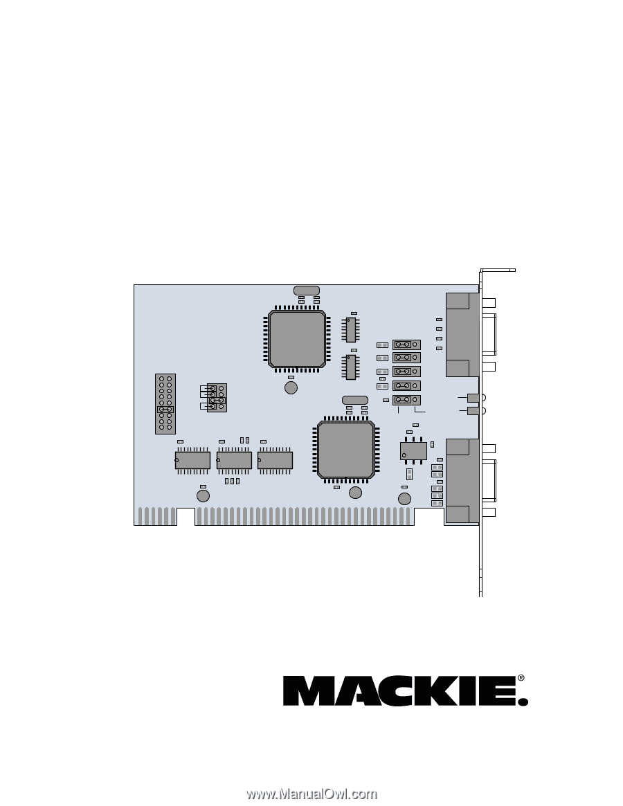
Serial•9 Installation Guide for the HDR24/96 Y2 Serial 9 Pin Card C16 R13 IRQ IRQ2/9 IRQ3 IRQ4 IRQ5 IRQ7 IRQ10 IRQ11 IRQ12 IRQ15 JB2 C4 I/O BASE ADDRESS BASE4 BASE5 BASE6 BASE8 JB1 R1 R2 - Mackie Serial9 | Installation Guide - Page 2
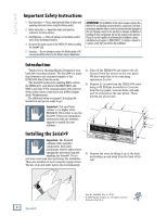
warnings on this Mackie product and in these operating instructions. 4. Disconnect the power source to the HDR24/96 before installing the Serial•9 Card. 5. Servicing - Do not attempt to service this Mackie product. All servicing should be referred to the Mackie Service Department. ATTENTION: The - Mackie Serial9 | Installation Guide - Page 3
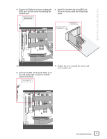
Guide 4) Remove the Phillips-head screw securing the MIDI card. Save the screw for installing the Serial•9 card. 4) Remove Screw from MIDI card bracket 6) Install the Serial the Serial•9 card into the slot 6b) Install Screw into Serial•9 card bracket ® MACKIE DESIGNS. ™ © 2000 ® MACKIE DESIGNS. - Mackie Serial9 | Installation Guide - Page 4
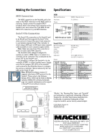
•9. Please refer to the Software Release Notes, which can be found on Mackie website's HDR24/96 software downloads page, for complete information on the support of Serial•9 for all software versions. MIDI Electrical Interface: MIDI 1.0 Specification Data Rate: 31.25 kb/sec Pinout: 61 95 MIDI
-
 1
1 -
 2
2 -
 3
3 -
 4
4
 |
 |
Installation Guide
for the HDR24/96
Serial•9
Serial•9
Serial•9
Serial•9
Serial•9
Dual Communication Card for the HDR24/96
IRQ
J2
J1
IRQ2/9
IRQ3
IRQ4
IRQ5
IRQ7
IRQ10
IRQ11
IRQ12
IRQ15
JB2
JB1
U2
C21
+
U3
R5 R4 R3
U1
U5
U4
U7
U8
Serial 9 Pin Card
U6
I/O BASE
ADDRESS
BASE4
BASE5
BASE6
BASE8
C4
JP2
JP3
DEVICE
DEVICE
CONTROLLER
JP4
JP5
JP1
C22
C5
C18
C6
R1 R2
R9
C3
C24
+
+
+
C23
+
C1
L3
L2
R10
C10
C2
D1
D3
D2
C11
R11
R14
C17
C19
C20
C14
C12
C15
C13
R12
C16
R13
C7
R6
C8
R8
Y1
Y2
R15
L5
L6
L4
L7
R7
L1
C9
+