Makita 5104 Owners Manual - Page 7
Assembly
 |
View all Makita 5104 manuals
Add to My Manuals
Save this manual to your list of manuals |
Page 7 highlights
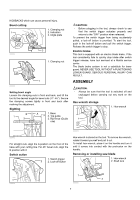
KICKBACKS which can cause personal injury. Bevel cutting 1 2 1. Clamping nut 2. Indication 3. Angle plate 008462 3 1. Clamping nut 1 008490 Setting bevel angle Loosen the clamping nuts in front and back, and tilt the tool to the desired angle for bevel cuts ( 0°- 45°). Secure the clamping screws tightly in front and back after marking the adjustment. Sighting B 1 2 A 1. Base 3 2. Top guide 3. Rip fence (Guide rule) CAUTION: • Before plugging in the tool, always check to see that the switch trigger actuates properly and returns to the "OFF" position when released. To prevent the switch trigger from being accidentally pulled, a lock-off button is provided. To start the tool, push in the lock-off button and pull the switch trigger. Release the switch trigger to stop. Electric brake This tool is equipped with an electric blade brake. If the tool consistently fails to quickly stop blade after switch trigger release, have tool serviced at a Makita service center. The blade brake system is not a substitute for lower guard. NEVER USE TOOL WITHOUT A FUNCTIONING LOWER GUARD. SERIOUS PERSONAL INJURY CAN RESULT. ASSEMBLY CAUTION: • Always be sure that the tool is switched off and unplugged before carrying out any work on the tool. Hex wrench storage 1. Hex wrench 1 008465 008463 For straight cuts, align the A position on the front of the base with your cutting line. For 45° bevel cuts, align the B position with it. Switch action 1. Switch trigger 2 2. Lock-off button Hex wrench is stored on the tool. To remove hex wrench, rotate it toward yourself and pull it out. To install hex wrench, place it on the handle and turn it until it comes into contact with the protrusion on the handle. Removing or installing saw blade 1. Hex wrench 2. Shaft lock 1 008464 1 2 008466 7
-
 1
1 -
 2
2 -
 3
3 -
 4
4 -
 5
5 -
 6
6 -
 7
7 -
 8
8 -
 9
9 -
 10
10 -
 11
11 -
 12
12 -
13
-
14
-
15
-
16
-
17
-
18
-
19
-
20
-
21
-
22
-
23
-
24
-
25
-
26
-
27
-
28
-
29
-
30
-
31
-
32
 |
 |
