Makita 9557PB Owners Manual - Page 6
Operation - angle grinder
 |
View all Makita 9557PB manuals
Add to My Manuals
Save this manual to your list of manuals |
Page 6 highlights
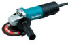
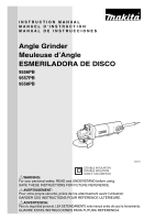
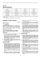
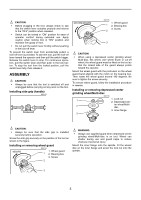
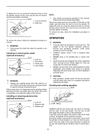
To tighten the lock nut, press the shaft lock firmly so that the spindle cannot revolve, then use the lock nut wrench and securely tighten clockwise. 006117 1. Lock nut wrench 1 2. Shaft lock 2 NOTE: • Use sander accessories specified in this manual. These must be purchased separately. Mount the rubber pad onto the spindle. Fit the disc on the rubber pad and screw the lock nut onto the spindle. To tighten the lock nut, press the shaft lock firmly so that the spindle cannot revolve, then use the lock nut wrench and securely tighten clockwise. To remove the disc, follow the installation procedure in reverse. To remove the wheel, follow the installation procedure in reverse. WARNING: • Only actuate the shaft lock when the spindle is not moving. Installing or removing flex wheel (optional accessory) 006118 1. Lock nut 1 2. Flex wheel 3 3. Plastic pad 2 4. Inner flange 4 OPERATION WARNING: • It should never be necessary to force the tool. The weight of the tool applies adequate pressure. Forcing and excessive pressure could cause dangerous wheel breakage. • ALWAYS replace wheel if tool is dropped while grinding. • NEVER bang or hit grinding disc or wheel onto work. • Avoid bouncing and snagging the wheel, especially when working corners, sharp edges etc. This can cause loss of control and kickback. • NEVER use tool with wood cutting blades and other sawblades. Such blades when used on a grinder frequently kick and cause loss of control leading to personal injury. WARNING: • Always use supplied guard when flex wheel is on tool. Wheel can scatter during use and guard helps to reduce chances of personal injury. Follow instructions for depressed center grinding wheel/ Multi-disc but also use plastic pad over wheel. See order of assembly on accessories page in this manual. Installing or removing abrasive disc (optional accessory) 006119 1. Lock nut 1 2. Abrasive disc 3 3. Rubber pad 2 CAUTION: • After operation, always switch off the tool and wait until the wheel has come to a complete stop before putting the tool down. Grinding and sanding operation 006122 15 A B ALWAYS hold the tool firmly with one hand on housing and the other on the side handle. Turn the tool on and then apply the wheel or disc to the workpiece. In general, keep the edge of the wheel or disc at an angle of about 15 degrees to the workpiece surface. During the break-in period with a new wheel, do not work the grinder in the B direction or it will cut into the workpiece. Once the edge of the wheel has been rounded off by use, the wheel may be worked in both A and B direction. 6
-
 1
1 -
 2
2 -
 3
3 -
 4
4 -
 5
5 -
 6
6 -
 7
7 -
 8
8 -
 9
9 -
 10
10 -
 11
11 -
 12
12 -
13
-
14
-
15
-
16
-
17
-
18
-
19
-
20
-
21
-
22
-
23
-
24
-
25
-
26
-
27
-
28
 |
 |