Makita BGA452 Owners Manual - Page 6
optional accessory - brush
 |
View all Makita BGA452 manuals
Add to My Manuals
Save this manual to your list of manuals |
Page 6 highlights
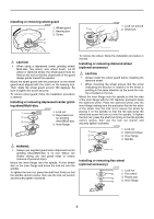
Installing or removing wheel guard 007218 1 1. Wheel guard 1 2. Bearing box 3. Screw 2 3 2 007220 1. Lock nut wrench 2. Shaft lock CAUTION: • When using a depressed center grinding wheel/ Multi-disc, flex wheel, wire wheel brush, cut-off wheel or diamond wheel, the wheel guard must be fitted on the tool so that the closed side of the guard always points toward the operator. Mount the wheel guard with the protrusion on the wheel guard band aligned with the notch on the bearing box. Then rotate the wheel guard around 180 degrees. Be sure to tighten the screw securely. To remove wheel guard, follow the installation procedure in reverse. Installing or removing depressed center grind- ing wheel/Multi-disc 007219 1 1. Lock nut 2. Depressed cen- 2 ter grinding 3 wheel/Multi-disc 3. Inner flange To remove the wheel, follow the installation procedure in reverse. Installing or removing diamond wheel (optional accessory) CAUTION: • Always install the wheel guard before installing the diamond wheel. • When mounting the wheel ensure that the arrow (indicating the direction of rotation) on the wheel is pointing in the same direction as the arrow for rotation provided on the tool. Mount the inner flange onto the spindle so that the side of the inner flange with the 7/8" diameter protrusion faces the diamond wheel. Place the diamond wheel onto the inner flange making sure the protrusion fits into the arbor of the wheel. Use the lock nut to secure the wheel by placing it on the spindle so that the flat side faces the wheel and screw the lock nut onto the spindle. To tighten the lock nut, press the shaft lock firmly so that the spindle cannot revolve, then use the lock nut wrench and securely tighten clockwise. 007238 1. Lock nut 1 2. Diamond wheel 2 3. Inner flange 3 7/8" 4. Spindle WARNING: • Always use supplied guard when depressed center grinding wheel/Multi-disc is on tool. Wheel can shatter during use and guard helps to reduce chances of personal injury. Mount the inner flange onto the spindle. Fit the wheel/ disc on the inner flange and screw the lock nut onto the spindle. To tighten the lock nut, press the shaft lock firmly so that the spindle cannot revolve, then use the lock nut wrench and securely tighten clockwise. 4 Installing or removing flex wheel (optional accessory) 007241 1 1. Lock nut 2 2. Flex wheel 3 3. Plastic pad 4 4. Inner flange 6
-
 1
1 -
 2
2 -
 3
3 -
 4
4 -
 5
5 -
 6
6 -
 7
7 -
 8
8 -
 9
9 -
 10
10 -
 11
11 -
 12
12 -
13
-
14
-
15
-
16
-
17
-
18
-
19
-
20
-
21
-
22
-
23
-
24
-
25
-
26
-
27
-
28
-
29
-
30
-
31
-
32
-
33
-
34
-
35
-
36
 |
 |
