Makita LC1230 Owners Manual - Page 8
workpiece.
 |
View all Makita LC1230 manuals
Add to My Manuals
Save this manual to your list of manuals |
Page 8 highlights
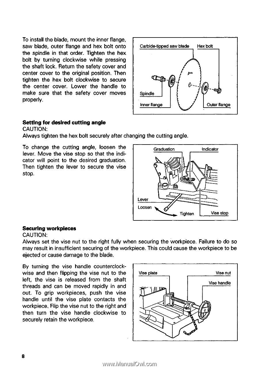
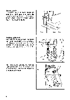
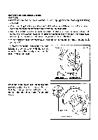
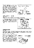
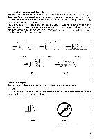
To install the blade, mount the inner flange, saw blade, outer flange and hex bolt onto the spindle in that order. Tighten the hex bolt by turning clockwise while pressing the shaft lock. Return the safety cover and center cover to the original position. Then tighten the hex bolt clockwise to secure the center cover. Lower the handle to make sure that the safety cover moves properly. Carbide•tipped saw blade Hex bolt Spindle Inner flange 6 Outer flan e Setting for desired cutting angle CAUTION: Always tighten the hex bolt securely after changing the cutting angle. To change the cutting angle, loosen the lever. Move the vise stop so that the indicator will point to the desired graduation. Then tighten the lever to secure the vise stop. Graduation Indicator Lever Loosen Tighten Vise stop Securing workplaces CAUTION: Always set the vise nut to the right fully when securing the workpiece. Failure to do so may result in insufficient securing of the workpiece. This could cause the workpiece to be ejected or cause damage to the blade. By turning the vise handle counterclockwise and then flipping the vise nut to the left, the vise is released from the shaft threads and can be moved rapidly in and out. To grip workpieces, push the vise handle until the vise plate contacts the workpiece. Flip the vise nut to the right and then turn the vise handle clockwise to securely retain the workpiece. Vise plate Vise nut Vise handle 0 8
-
 1
1 -
2
-
 3
3 -
 4
4 -
 5
5 -
 6
6 -
 7
7 -
 8
8 -
 9
9 -
 10
10 -
 11
11 -
 12
12 -
 13
13 -
14
-
15
-
16
-
17
-
18
-
19
-
20
 |
 |