Marantz SR4021 SR4021 User Manual - Page 13
Connecting Video Components, Connecting The Remote Control Jacks - model
 |
View all Marantz SR4021 manuals
Add to My Manuals
Save this manual to your list of manuals |
Page 13 highlights
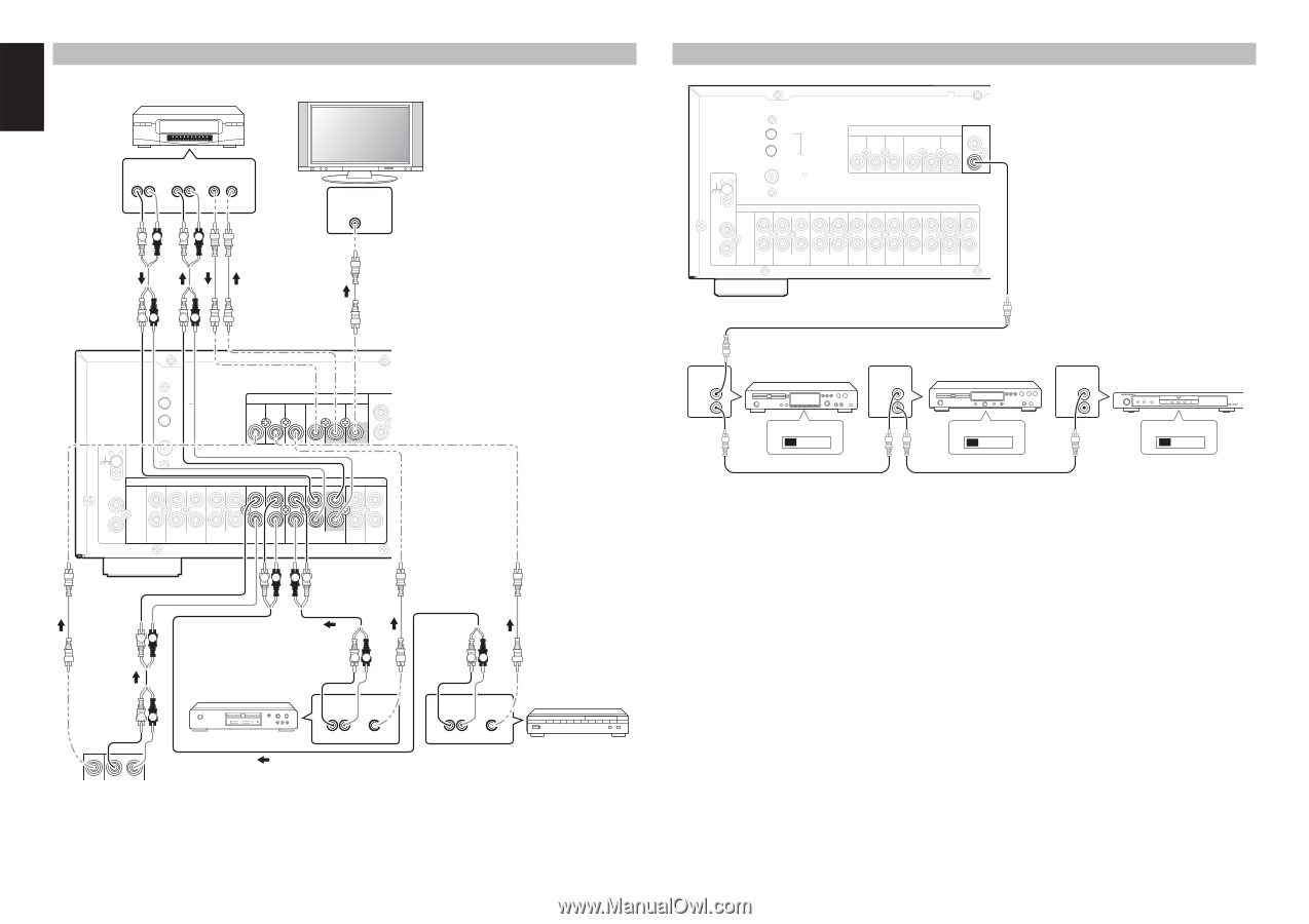
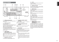
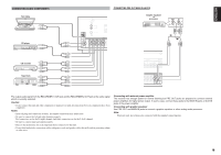
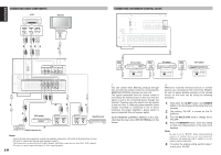
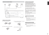
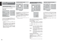
ENGLISH CONNECTING VIDEO COMPONENTS VCR Monitor AUDIO AUDIO VIDEO OUT IN OUT IN L R LR LR LR VIDEO IN CVBS CONNECTING THE REMOTE CONTROL JACKS GND ANTENNA AM GND FM (75 ) AUX IN DSS IN VIDEO DVD IN VCR IN OUT MONITOR OUT REMOTE CONTROL IN OUT PHONO IN L R AUDIO IN IN OUT IN OUT IN IN IN IN OUT CD RECORDER 1 (CD-R) RECORDER 2 (TAPE) AUX DSS DVD VCR PRE OUT MAIN IN LR LR ANTENNA AM GND GND FM (75 ) AUX IN DSS IN VIDEO DVD IN VCR IN OUT MONITOR OUT REMOTE CONTROL IN OU REMOTE CONTROL IN OUT CD recorder EXTERNAL INTERNAL REMOTE CONTROL IN OUT CD player EXTERNAL INTERNAL REMOTE CONTROL IN OUT DVD player STANDBY POWER ON/STANDBY DVD PLAYER DV4600 VIRTUAL FL OFF OPEN/CLOSE EXTERNAL INTERNAL PHONO IN L R AUDIO IN IN OUT IN OUT IN IN IN IN OUT CD RECORDER 1 (CD-R) RECORDER 2 (TAPE) AUX DSS DVD VCR PRE OUT MAIN IN LR RL LR DVD player LR OUT OUT VIDEO L R VIDEO camera etc.. LR AUDIO VIDEO OUT OUT LR LR AUDIO VIDEO OUT OUT LR MODEL NO. Satellite tuner q You can control other Marantz products through this unit with the remote control by connecting the REMOTE CONTROL terminals on each unit. The signal transmitted from the remote control is received by the remote sensor on this unit. Then the signal is sent to the connected device through this terminal. Therefore you only need to aim the remote at one unit. Also, if a Marantz power amplifier (some models excluded) is connected to one of these terminals, the power amplifier's, power switch is synchronized with this unit's power switch. Set the REMOTE CONTROL SWITCH on the units, other than the main unit to EXT.(EXTERNAL) for this feature. Notes: • Insert all plugs and connectors securely. Incomplete connections will result in the generation of noise. • Be sure to connect the left and right channels properly. Red connectors are used for the R (right) channel, and white connectors are used for L (left) channel. • Be sure to connect input and output of video signal properly. 10 w Whenever external infrared sensors or similar devices are connected to RC-5 IN of the SR4021, be sure to always disable operation of the infrared sensor on the main unit by using the following procedure. 1. Hold down the SLEEP button and DIMMER button on the front panel at the same time for 3 seconds. 2. The setting "IR=ON" is shown on the FL DISPLAY. 3. Turn the MULTI JOG knob to change this to "IR=OFF". 4. Press the MEMORY button. Once this setting is made, the infrared sensor on the main unit is disabled. Note: Be sure to set to "IR=ON" when external infrared sensors or similar devices are not connected. Otherwise, the main unit will be unable to receive remote control commands. 5. To restore the original setting, perform steps 1 to 4 to set to "IR=ON".
-
 1
1 -
2
-
3
-
4
-
5
-
6
-
7
-
 8
8 -
 9
9 -
 10
10 -
 11
11 -
 12
12 -
 13
13 -
 14
14 -
 15
15 -
 16
16 -
 17
17 -
 18
18 -
19
-
20
-
21
-
22
 |
 |