Marantz SR6001 SR6001 User Manual - Page 12
Remote Control, Operation
 |
View all Marantz SR6001 manuals
Add to My Manuals
Save this manual to your list of manuals |
Page 12 highlights
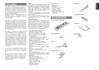
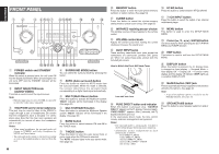
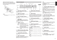
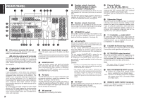
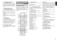
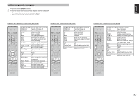
ENGLISH !9 AUDIO IN/OUT (TV, DVD, VCR, DSS, TAPE, CD/CDR) These are the analog audio inputs and outputs. There are 6 audio inputs and 3 audio outputs. The audio jacks are nominally labeled for cassette tape decks, compact disc players, DVD players and etc.... The audio inputs and outputs require RCA-type connectors. @0 DIGITAL INPUT (Dig.1 - 5) / OUTPUT (coaxial, optical) These are the digital audio inputs and outputs. There are 2 digital inputs with coaxial jacks, 3 with optical jacks. The inputs accept digital audio signals from a compact disc, LD, DVD, or other digital source component. For digital output, there is 1 coaxial output and 1 optical output. The digital outputs can be connected to MD recorders, CD recorders, DAT decks, or other similar components. @1 VIDEO IN/OUT (TV, DVD, VCR, DSS) These are the video inputs and outputs. There are 4 video inputs and 1 video output and each one includes both composite video and S-video configurations. Connect VCRs, DVD players, and other video components to the video inputs. The 1 video output channel can be used to connected to video tape recorders for making recordings. @2 HDMI INPUT / OUTPUT This unit has 2 HDMI inputs and 1 HDMI output. The input function can be selected from the OSD menu system. (See page 19) REMOTE CONTROL OPERATION FUNCTION AND OPERATION The provided remote control unit is a universal remote controller. The POWER button, numeric buttons and control buttons are used in common across different input source components. The input source controlled with the remote control unit changes when one of the input selector buttons is pressed. ‹5 z x c v b n m , . ⁄0 ⁄1 ⁄2 ⁄3 ⁄4 ⁄5 ⁄6 LEARN SEND SOURCE l/ SET SLEEP DISPLAY OFF ON P.DIRECT SURROUND AUTO 12 LIP SYNC/ dts INPUT 3 BAND CS EX/ES VIRTUAL T.MODE 456 M-CH ST 7 STEREO 8 NIGHT 9 P.SCAN 7.1CH IN A/D HT-EQ CL 0 +10 MEMO CH/ CAT SPKR A/B MUTE VOLUME MULTI/ CAT M-SPKR INFO MENU T.TONE /SET UP ENTER EXIT REC T.DISP PTY F.DIRECT - PRESET + - TUNING + DISC+ ANGLE SUB TITLE AUDIO CH-SEL V-OFF ATT. BASS TV DVD TREBLE VCR DSS TUNER CD CDR MD TAPE AUX1 AUX2 AMP ⁄7 ⁄8 ⁄9 ¤0 ¤1 ¤2 ¤3 ¤4 ¤5 ¤6 ¤7 ¤8 ¤9 ‹0 ‹1 ‹2 ‹3 ‹4 z LEARN indicator Indicates when the remote controller is in the LEARN mode. x SET button This button is used to enter learn mode and preset mode. c / SOURCE ON/OFF button This button is used to turn a specific source (such as a DVD player) on or off independently from the rest of the system. v SLEEP button This button is used for setting the sleep timer. b DISPLAY button Selects the display mode for the front display of the SR6001. n Numeric buttons These buttons are used to switch between 0 to +10 of the source components. If the source is set to the amplifier, these buttons are used to perform operations. (When AMP mode is selected) 1/AUTO button Used to select auto surround. 2/Dolby button Used to select DOLBY mode. 3/dts button Used to select dts mode. 4/CSII button Used to select CSII mode. 5/EX/ES button Used to select EX/ES mode. 6/VIRTUAL button Used to select VIRTUAL mode. 7/M-CH ST button Used to select Multi Channel Stereo. 8/STEREO button Used to select STEREO mode. 9/NIGHT button Pressing this button prevents the Dolby Digital signal from playback at a loud voice. This function reduces the voice by 1/3 to 1/4 at maximum. Thus, it eliminates the occurrence of an abruptly loud voice at night. However, the function is valid only in the case when the Dolby Digital signal is entered into OPTICAL or COAXIAL and data to compress the voice exists in the signal to be played back. When this button is pressed, the "NIGHT" indicator is illuminated. 0/7.1CH IN button Press this button to select the output of an external multi channel decoder. (+10) A/D button Used to switch between the analog and digital inputs. m CL (Clear) button This button is used to erase the memory or program of a source. , SPKR A/B button Used to select the speaker system. The speaker system is switched in the following sequence. A → B → A+B → off . CH/CAT3 (UP) / 4 (DOWN) buttons These buttons are used to change channels. ⁄0 MULTI/CAT button (When AMP mode is selected) Used to turn on and off multi room. ⁄1 INFO button (When AMP mode is selected) When this button is pressed, the current setting are displayed on the TV monitor. ⁄2 T.TONE/SET UP button (When AMP mode is selected) Used to enter the test tone menu. REMOTE CONTROLLER RC5001SR 9
-
 1
1 -
2
-
3
-
4
-
5
-
6
-
 7
7 -
 8
8 -
 9
9 -
 10
10 -
 11
11 -
 12
12 -
 13
13 -
 14
14 -
 15
15 -
 16
16 -
 17
17 -
18
-
19
-
20
-
21
-
22
-
23
-
24
-
25
-
26
-
27
-
28
-
29
-
30
-
31
-
32
-
33
-
34
-
35
-
36
-
37
-
38
-
39
-
40
-
41
-
42
-
43
-
44
-
45
-
46
-
47
-
48
-
49
-
50
-
51
-
52
-
53
-
54
-
55
-
56
-
57
-
58
-
59
-
60
-
61
-
62
-
63
-
64
-
65
-
66
-
67
-
68
-
69
-
70
-
71
 |
 |
