Marantz SR8000 Service Manual - Page 32
Service Program
 |
View all Marantz SR8000 manuals
Add to My Manuals
Save this manual to your list of manuals |
Page 32 highlights
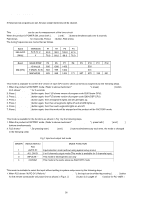
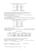
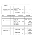
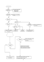
8. SERVICE PROGRAM REMARK If these service programs are set, All user preset memories will be cleared. 1. FACTORY mode (Tracking point memory) This FACTORY mode can be use for measurement of the tuner circuit. When the product is POWER ON, press both [ MEMO ] and [ F/P ] buttons simultaneously over 3 seconds. FLD shows "FACTORY" for 3 seconds. Press [ F/P] button, FLD shows "PRESET SEL". The tuning frequencies are memorized as follows. Band FM AUTO [MHz] VERSION K, N, S, U F P1 90.0 78.0 P2 98.0 83.0 P3 106.0 88.0 P4 87.5 76.0 Band SCAN STEP P5 P6 P7 P8 P9 P10 P11 P12 10 kHz(U) 600 1000 1400 520 AM [kHz] 9 kHz(K, N, S) 603 999 1404 531 MW/LW(N) 603 999 1404 171 207 270 152 531 2. Version of microprocessor (CPU) and FLD segment check mode This mode is available to confirm the version of each CPU and to check all luminous segments by the following steps. 1. When the product is FACTORY mode ( Refer to above mentioned "1. FACTORY mode"), press [ DISPLAY OFF ] button. FLD shows "SERVICE" for 2 seconds. 2. Press [ DISPLAY OFF ] button again, then FLD shows version of program code QU01(main CPU). 3. Press [ DISPLAY OFF ] button again, then FLD shows version of program code Q691(DSP CPU). 4. Press [ DISPLAY OFF ] button again, then all segments lights and all LED lights up. 5. Press [ DISPLAY OFF ] button again, then then all segments lights off and all LED lights up. 6. Press [ DISPLAY OFF ] button again, then then each segments lights on and off. 7. Press [ DISPLAY OFF ] button again, then this mode will be stopped and the product will be FACTORY mode. 3. Input and output test mode This mode is available for the functions as shown in Fig 1 by the following steps. 1. When the product is FACTORY mode ( Refer to above mentioned "1. FACTORY mode"), press both [ MEMO ] and [ MODE] buttons simultaneously. 2. FLD shows "AUTO D1". By pressing both [ MEMO ] and [ MODE ] buttons simultaneously each time, the mode is changed in the following order. Fig 1 Input and output test mode ORDER 1 2 3 4 INDICATION for FLD AUTO D1 ALL CH D1 INPULSE -- CD/DIG1 MODE FUNCTION Input selection mode (without using system setup menu) 5 or 6 channels output mode (This mode is available for 2 channels input) This mode is development use only This mode is the same status as FACTORY mode 3.1. Input selection mode (without setting to system setup menu) This mode is available to select the input without setting to system setup menu by the following steps. 1. When FLD shows "AUTO D1"( Refer to "3. Input and output test mode"), the input can be shifted by pressing [ MODE ] button for the remote commander only each time as shown in Fig 2. ( [ MODE ] button is in page4 of AMP function for RC-18SR*) 56
-
 1
1 -
2
-
3
-
4
-
5
-
6
-
7
-
8
-
9
-
10
-
11
-
12
-
13
-
14
-
15
-
16
-
17
-
18
-
19
-
20
-
21
-
22
-
23
-
24
-
25
-
26
-
 27
27 -
 28
28 -
 29
29 -
 30
30 -
 31
31 -
 32
32 -
 33
33 -
 34
34 -
 35
35 -
 36
36 -
 37
37 -
38
-
39
-
40
-
41
-
42
-
43
-
44
-
45
-
46
-
47
-
48
-
49
-
50
-
51
-
52
-
53
-
54
-
55
-
56
-
57
-
58
-
59
 |
 |
