Maytag AMC5143AAS Installation Instructions
Maytag AMC5143AAS - Amana - 1.4 cu. ft. Countertop Microwave Oven Manual
 |
UPC - 719881136790
View all Maytag AMC5143AAS manuals
Add to My Manuals
Save this manual to your list of manuals |
Maytag AMC5143AAS manual content summary:
- Maytag AMC5143AAS | Installation Instructions - Page 1
INSTALLATION INSTRUCTIONS BUILT-IN KIT MODEL UXA0024AXB/Q/W/S IMPORTANT:This Built-In Kit is desinged for and approved only for those AMANA AMC5143AAB/W/Q/S Microwave Ovens specifying Built-In Kit UXA0024AXB/Q/W/S on rating label on the oven. CAUTION: THIS OVEN REQUIRES INSTALLATION INTO A - Maytag AMC5143AAS | Installation Instructions - Page 2
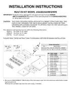
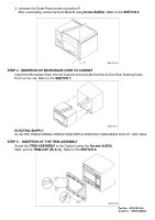
strong and thick enough to support the weight of the oven and : While the proper functioning of the oven does not require that opening be enclosed 1 STEP 2 : TRIM ASSEMBLY Position the ASSY TRIM and SIDES as shown in SKETCH 2. Make sure that the ASSY TRIM and SIDES are lined - Maytag AMC5143AAS | Installation Instructions - Page 3
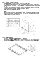
it to the Duct Upper & Duct Back-A along the Duct Upper & Duct Back-A. Refer to the SKETCH 4. SKETCH 4 2. Place the Assembled parts(Duct Upper & Duct Back A) on the Microwave Oven in SKETCH 5. Screw the Assembled parts(Duct Upper & Duct Back A) using Screw B(2EA). Refer to the SKETCH 5. SKETCH 5 - Maytag AMC5143AAS | Installation Instructions - Page 4
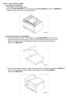
TO CABINET Insert the Microwave Oven into the Cabinet and coincide the foot & Duct-Rain foaming holes. Put it on the rail. Refer to the SKETCH 7. SKETCH 7 ELECTRIC SUPPLY PLUG THE THREE-PRONG POWER CORD INTO A PROPERLY GROUNDED OUTLET, 120V, 60Hz. STEP 5 : INSERTION OF THE TRIM ASSEMBLY Screw the - Maytag AMC5143AAS | Installation Instructions - Page 5
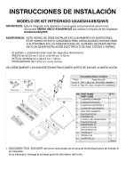
KIT INTEGRADO UXA0024AXB/Q/W/S IMPORTANTE: Este kit integrado está diseñado y homologado exclusivamente para hornos microondas AMANA AMC5143AAB/W/Q/S que exhiban la etiqueta de kits MSMR1 Tornillo-B WE,TH,+,M4,L12,ZPC(YEL),WASHER NO. PART NAME PART CODE Q'TY 1 CUBIERTA SUPERIOR 1 12 2 - Maytag AMC5143AAS | Installation Instructions - Page 6
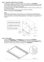
kilos> y los trabajos de instalación. En primer lugar, perfore los 4 orificios utilizando la plantilla y coloque el raíl para cubiertas en la parte inferior del bastidor. Haga coincidir los orificios del raíl con los orificios inferiores del bastidor. Atornille el raíl utilizando el tornillo B (4EA - Maytag AMC5143AAS | Installation Instructions - Page 7
PASO 3: INSTALACIÓN DE CUBIERTAS a. Instalación de cubiertas inferiores Para empezar, coloque el horno boca abajo. Fije la CUBIERTA INFERIOR a la base del horno utilizando el tornillo B (4EA) como se muestra en el ESQUEMA 3. Teniendo cuidado, vuelva a colocar el horno en su posición inicial. ESQUEMA - Maytag AMC5143AAS | Installation Instructions - Page 8
TIERRA ADECUADA, 120V, 60Hz. PASO 5: INSERCIÓN DEL RESGUARDO Fije el RESGUARDO al bastidor utilizando el tornillo A (4EA). A continuación, coloque las CUBIERTAS (D) e (I). Consulte el ESQUEMA 8. ESQUEMA 8 Part No.: 8101P615-60 Código No.: DE68-02898A
-
 1
1 -
 2
2 -
 3
3 -
 4
4 -
 5
5 -
 6
6 -
 7
7 -
8
 |
 |
INSTALLATION INSTRUCTIONS
BUILT-IN KIT MODEL UXA0024AXB/Q/W/S
IMPORTANT:
This Built-In Kit is desinged for and approved only for those
AMANA
AMC5143AAB/W/Q/S
Microwave Ovens specifying Built-In Kit
UXA0024AXB/Q/W/S
on rating label on the oven.
CAUTION:
THIS OVEN
REQUIRES INSTALLATION INTO A CABINET STRUCTURE ONLY. THIS
OVEN IS NOT DESIGNED FOR USE IN NON-CABINET INSTALLTIONS OR FREE-
STANDING APPLICATIONS ADJACENT TO (WITHIN 2 FEET OF) ANY GAS OR ELEC-
TRIC RANGE, COOKTOP OR OVEN.
The cabinet or wall opening must be within the following dimensions :
WIDTH
22-13/64" to 22-19/64"
HEIGHT
16-15/16" to 17-1/64"
DEPTH
15-3/4" minimum
PLEASE READ THESE INSTRUCTIONS THOROUGHLY BEFORE BEGINNING INSTALLATION!
❉
Be sure to DISCONNECT THE PLUG of the microwave oven from the electrical outlet before install-
ing the built-in kit.
Remove the turntable tray from the oven cavity, if needed.
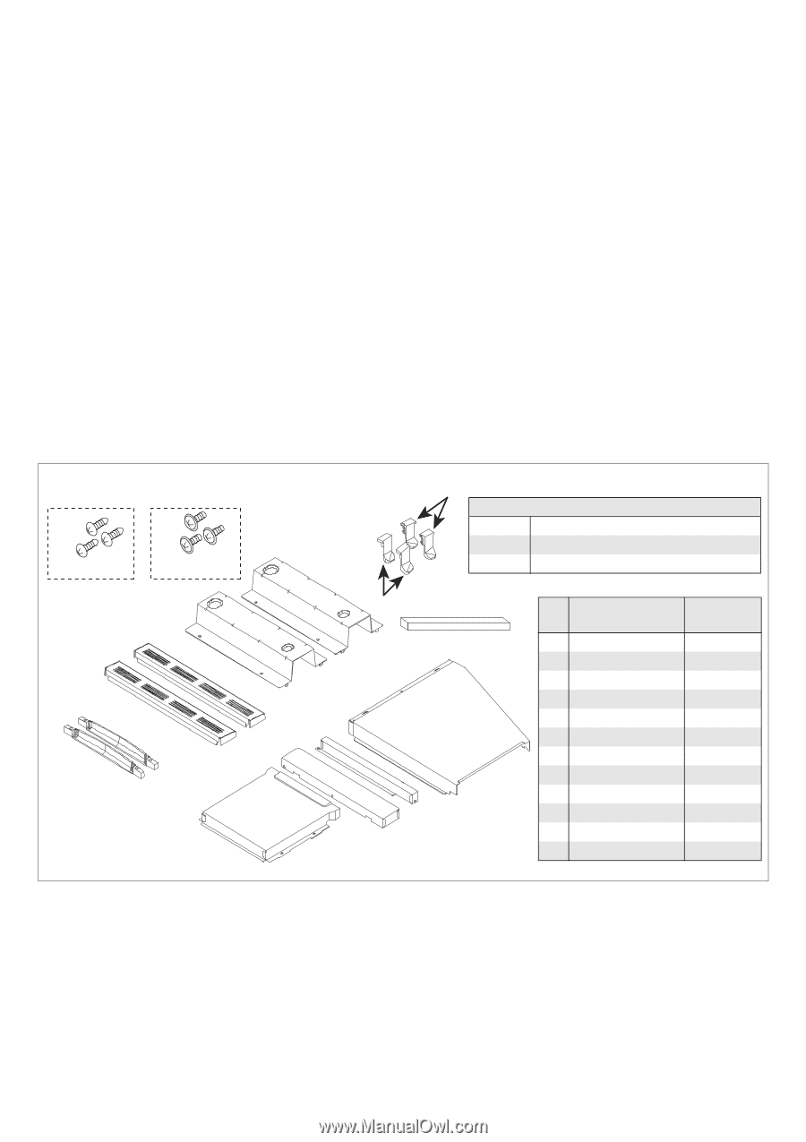
1
12
2
3
7
8
9
4
5
6
10
11
Screw A Type
Screw B Type
NO.
PART NAME
PART CODE
Q’TY
1
DUCT UPPER
1
2
DUCT BOTTOM
1
3
DUCT BACK A
1
4
DUCT BACK B
1
5
DUCT-RAIL
2
6
ASSY TRIM
2
7
TRIM -SIDE
2
8
TRIM -CAP(L)
2
9
TRIM -CAP(R)
2
10
SCREW A
4
11
SCREW B
17
12
CUSHION
1(168mm)
Screw Information
Part
Specification
Screw-A
TH,+, M4,L16,
ZPC(YEL), MSMR1
Screw-B
WE,TH,+,M4,L12,ZPC(YEL),WASHER