Maytag MEC4436AAW Installation Instructions
Maytag MEC4436AAW - 36 Inch Electric Cooktop Manual
 |
View all Maytag MEC4436AAW manuals
Add to My Manuals
Save this manual to your list of manuals |
Maytag MEC4436AAW manual content summary:
- Maytag MEC4436AAW | Installation Instructions - Page 1
PAGES OF THIS INSTRUCTION SHEET. OUTSIDE WIRING Your local utility company will tell you whether the present electric service to your home supply; the neutral conductor is not required for the operation of the appliance. The potential at the power supply electrical connections shall be 150-volts- - Maytag MEC4436AAW | Installation Instructions - Page 2
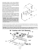
ARE NOT DESIGNED TO WITHSTAND THE HEAT PRODUCED BY THE NORMAL SAFE OPERATION OF A LISTED APPLIANCE. DISCOLORATION OR DAMAGE, SUCH AS DELAMINATION, MAY OCCUR. "A" COUNTER TOP BASE CABINET If MIN. FURNISHED AND INSTALLED BY MANUFACTURER (CONNECT TO 240/120-VOLT ELECTRICAL SERVICE.) FIGURE 1 2 - Maytag MEC4436AAW | Installation Instructions - Page 3
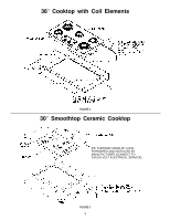
36² Cooktop with Coil Elements FIGURE 2 30² Smoothtop Ceramic Cooktop 3/8² FLEXIBLE CABLE 48² LONG FURNISHED AND INSTALLED BY MANUFACTURER (CONNECT TO 240/120 VOLT ELECTRICAL SERVICE) FIGURE 3 3 - Maytag MEC4436AAW | Installation Instructions - Page 4
ELÉCTRICO LOCAL INSTRUCCIONES DE INSTALACIÓN Unidades eléctricas de superficie montadas en el mostrador LEA LAS "INSTRUCCIONES DE SEGURIDAD" EN EL MANUAL DE CUIDADO Y USO ANTES DE USAR LA UNIDAD Para garantizar los mejores resultados en el servicio, el funcionamiento apropiado y la máxima - Maytag MEC4436AAW | Installation Instructions - Page 5
de la caja del quemador, quite las cuatro (4) unidades y los recipientes de goteo de la superficie. Quite los cuatro (4) tornillos de montaje de la parte superior principal. (Las lengüetas laterales de las aberturas del elemento.) PRECAUCIÓN: NO QUITE EL ALAMBRE VERDE DE CONEXIÓN A TIERRA DE LA - Maytag MEC4436AAW | Installation Instructions - Page 6
Superficie para cocinar con elementos de espiral de 36² FRENTE DE LA UNIDAD 3 3/8² DE PROFUNDIDAD CONDUCTOR DEL ALAMBRE DE 6² CABLE FLEXIBLE DE 1/2² DE 36² DE LARGO, PROVISTO E INSTALADO POR EL FABRICANTE (CONECTE A UN SERVICIO ELÉCTRICO DE 240/120 VOLTIOS.) 7/8² DERECHO TÍPICO 3 3/8² MÍNIMAS - Maytag MEC4436AAW | Installation Instructions - Page 7
CURITÉ" DANS LE MANUEL DE L'UTILISATEUR AVANT D'UTILISER L'APPAREIL Pour assurer un fonctionnement correct et efficient et des résultats optimums au niveau du service après-vente, la pose et le réglage initiaux doivent être réalisés par le revendeur, son prestataire agréé ou par la compagnie de gaz - Maytag MEC4436AAW | Installation Instructions - Page 8
d'un minimum de 5 po du bas des armoires." ATTENTION : CERTAINES ARMOIRES ET CERTAINS MATÉRIAUX DE CONSTRUCTION NE SONT PAS CONÇUS POUR SUPPORTER LA CHALEUR PRODUITE LORS DU FONCTIONNEMENT NORMAL D'UN APPAREIL. UNE DÉCOLORATION OU DES DÉGÂTS TELS QUE LA DÉLAMINATION PEUVENT SE PRODUIRE. "A" DESSUS - Maytag MEC4436AAW | Installation Instructions - Page 9
Plaque de cuisson de 91,4 cm avec éléments tubulaires DEVANT DE LA PLAQUE 50,2 CM MIN. 8,6 CM DE PROFONDUR CÂBLE FLEXIBLE DE 13 MM DE DIAMÈTRE ET 91,4 CM DE LONG FOURNI ET POSÉ EN USINE (RACCORDER À UNE ALIMENTATION ÉLECTRIQUE DE 240/120 V) FIL CONDUCTEUR DE 15,2 CM 6,7 CM MIN. 0,9 CM ARRONDI
-
 1
1 -
 2
2 -
 3
3 -
 4
4 -
 5
5 -
 6
6 -
 7
7 -
8
-
9
 |
 |
IMPORTANT - PLEASE KEEP FOR THE USE OF THE LOCAL ELECTRICAL INSPECTOR
INSTALLATION INSTRUCTIONS
Electric Counter Mounted Surface Units
READ °SAFETY INSTRUCTIONS± IN USE & CARE BOOK BEFORE USING UNIT
In order to assure the best results in service, proper operation and maximum efficiency, the original installation and adjustment
should be made by your dealer, his authorized agent, or by your local utility company before you attempt to operate the surface
unit.
LOCATION
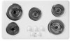
Place unit where it will be well lighted. For proper cooking results, it must be level. THESE ELECTRIC COUNTER MOUNTED
SURFACE UNITS ARE APPROVED FOR INSTALLATION IN COMBUSTIBLE CABINETRY. SEE INSTALLATION
DIAGRAM FOR THE APPROPRIATE UNIT ON THE FOLLOWING PAGES OF THIS INSTRUCTION SHEET.
OUTSIDE WIRING
Your local utility company will tell you whether the present
electric service to your home is adequate. It may be
necessary to increase the size of the wiring to the house and
service switch to take care of the electrical load demanded
by the surface unit and/or oven. The wattage (K.W. rating)
load for the range is specified on the name plate on the unit.
HOUSE WIRING
Most local building regulations and codes require that all
electrical wiring be done by licensed electricians. All wiring
should conform to Local and National Electrical Codes. This
unit requires a single phase three wire 120/240 or a 120/208
volt, 60 Hz, AC circuit. Wiring codes require that a separate
circuit be run from the main entrance panel to the unit and
that it be equipped with separate disconnect switch and
fuses, either in the main entrance panel or in a separate
switch and fuse box.
UNIT CONNECTIONS
This unit is supplied with a 240/208 volt wiring system
consisting of 2 insulated conductors and 1 bare grounding
wire for use on a 3 wire 120/240 or a 120/208 volts, 60 Hz AC
branch circuit. Connect only to a 3-wire, 120/240-volt power
supply; the neutral conductor is not required for the
operation of the appliance. The potential at the power supply
electrical connections shall be 150-volts-to-ground or less.
The flexible armored conduit supplied with the unit must be
connected to an approved electrical junction box by means
of an approved conduit to box connector.
THE BARE WIRE IN THE UNIT CONDUIT IS CONNECTED
TO THE FRAME OF THE UNIT. THE FRAME OF THE UNIT
IS GROUNDED TO NEUTRAL OF THE BRANCH CIRCUIT
ONLY
WHEN THIS BARE WIRE IS CONNECTED TO THE
NEUTRAL (WHITE) WIRE OF THE BRANCH CIRCUIT. If
used on new branch-circuit installations (1996 NEC), mobile
homes, recreational vehicles, or in an area where local
codes prohibit grounding through the neutral conductor, the
bare wire at the end of the unit conduit must be used to
ground the unit in accordance with local code. The red and
black wires must be connected to two conductors (red and
black) of the branch circuit. The neutral (white) wire of the
branch circuit must be properly insulated. Connect all wires
to the branch circuit with approved connectors. Use copper
or aluminum wire. If aluminum wire is used, use connectors
recognized for joining aluminum to copper.
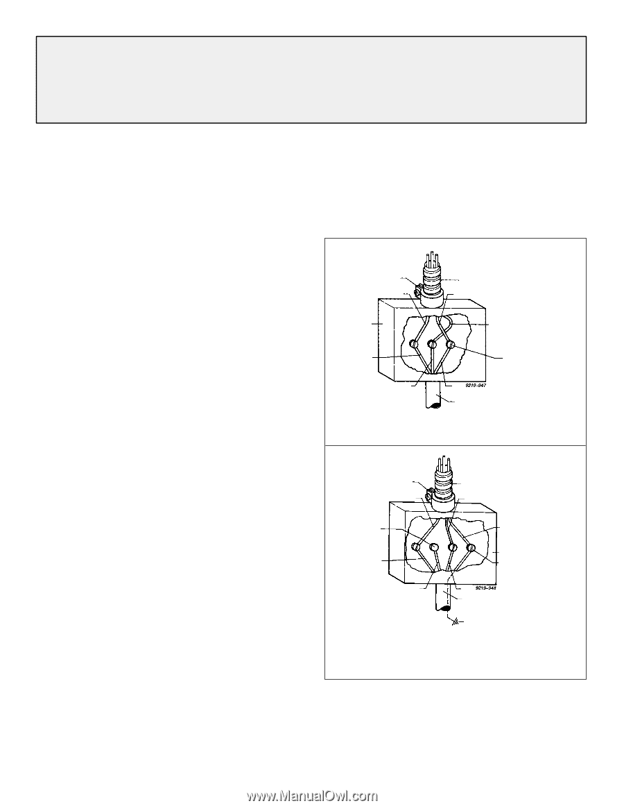
RANGE GROUNDED THROUGH NEUTRAL CONDUCTOR
WIRING METHOD IF CODE DOES NOT PERMIT GROUNDING
THROUGH NEUTRAL CONDUCTOR & ALSO REQUIRED IN MOBILE
HOMES.
WARNING:
Be sure UNIT is DISCONNECTED from
POWER SUPPLY before examining any of the electrical
equipment.
8101P480-60
(05-02-00)
RED
BLACK
RANGE CONDUIT
BARE
APPROVED
CONNECTOR
APPROVED
BOX
L1
L2
NEUTRAL
APPROVED INSULATED
CONNECTIONS
BRANCH CIRCUIT
(POWER SUPPLY)
APPROVED
CONNECTOR
BLACK
INSULATED
L1
NEUTRAL
RANGE CONDUIT
RED
BARE
APPROVED BOX
APPROVED INSULATED
CONNECTIONS
L2
SEPARATE GROUND
BRANCH CIRCUIT
(POWER SUPPLY)