Maytag MEC4436AAW Installation Instructions - Page 1
Maytag MEC4436AAW - 36 Inch Electric Cooktop Manual
 |
View all Maytag MEC4436AAW manuals
Add to My Manuals
Save this manual to your list of manuals |
Page 1 highlights
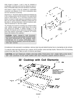
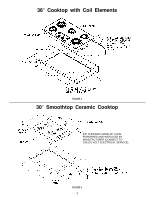
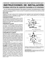
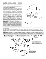
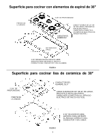
IMPORTANT - PLEASE KEEP FOR THE USE OF THE LOCAL ELECTRICAL INSPECTOR INSTALLATION INSTRUCTIONS Electric Counter Mounted Surface Units READ "SAFETY INSTRUCTIONS" IN USE & CARE BOOK BEFORE USING UNIT In order to assure the best results in service, proper operation and maximum efficiency, the original installation and adjustment should be made by your dealer, his authorized agent, or by your local utility company before you attempt to operate the surface unit. LOCATION Place unit where it will be well lighted. For proper cooking results, it must be level. THESE ELECTRIC COUNTER MOUNTED SURFACE UNITS ARE APPROVED FOR INSTALLATION IN COMBUSTIBLE CABINETRY. SEE INSTALLATION DIAGRAM FOR THE APPROPRIATE UNIT ON THE FOLLOWING PAGES OF THIS INSTRUCTION SHEET. OUTSIDE WIRING Your local utility company will tell you whether the present electric service to your home is adequate. It may be necessary to increase the size of the wiring to the house and service switch to take care of the electrical load demanded by the surface unit and/or oven. The wattage (K.W. rating) load for the range is specified on the name plate on the unit. HOUSE WIRING Most local building regulations and codes require that all electrical wiring be done by licensed electricians. All wiring should conform to Local and National Electrical Codes. This unit requires a single phase three wire 120/240 or a 120/208 volt, 60 Hz, AC circuit. Wiring codes require that a separate circuit be run from the main entrance panel to the unit and that it be equipped with separate disconnect switch and fuses, either in the main entrance panel or in a separate switch and fuse box. APPROVED CONNECTOR BLACK RANGE CONDUIT RED APPROVED BOX BARE L1 APPROVED INSULATED CONNECTIONS NEUTRAL L2 BRANCH CIRCUIT (POWER SUPPLY) RANGE GROUNDED THROUGH NEUTRAL CONDUCTOR UNIT CONNECTIONS This unit is supplied with a 240/208 volt wiring system consisting of 2 insulated conductors and 1 bare grounding wire for use on a 3 wire 120/240 or a 120/208 volts, 60 Hz AC branch circuit. Connect only to a 3-wire, 120/240-volt power supply; the neutral conductor is not required for the operation of the appliance. The potential at the power supply electrical connections shall be 150-volts-to-ground or less. The flexible armored conduit supplied with the unit must be connected to an approved electrical junction box by means of an approved conduit to box connector. APPROVED CONNECTOR BLACK INSULATED L1 RANGE CONDUIT RED BARE APPROVED BOX APPROVED INSULATED CONNECTIONS THE BARE WIRE IN THE UNIT CONDUIT IS CONNECTED TO THE FRAME OF THE UNIT. THE FRAME OF THE UNIT IS GROUNDED TO NEUTRAL OF THE BRANCH CIRCUIT ONLY WHEN THIS BARE WIRE IS CONNECTED TO THE NEUTRAL (WHITE) WIRE OF THE BRANCH CIRCUIT. If used on new branch-circuit installations (1996 NEC), mobile homes, recreational vehicles, or in an area where local codes prohibit grounding through the neutral conductor, the bare wire at the end of the unit conduit must be used to ground the unit in accordance with local code. The red and black wires must be connected to two conductors (red and black) of the branch circuit. The neutral (white) wire of the branch circuit must be properly insulated. Connect all wires to the branch circuit with approved connectors. Use copper or aluminum wire. If aluminum wire is used, use connectors recognized for joining aluminum to copper. NEUTRAL L2 BRANCH CIRCUIT (POWER SUPPLY) SEPARATE GROUND WIRING METHOD IF CODE DOES NOT PERMIT GROUNDING THROUGH NEUTRAL CONDUCTOR & ALSO REQUIRED IN MOBILE HOMES. WARNING: Be sure UNIT is DISCONNECTED from POWER SUPPLY before examining any of the electrical equipment. 8101P480-60 (05-02-00)
-
 1
1 -
 2
2 -
 3
3 -
 4
4 -
 5
5 -
 6
6 -
 7
7 -
8
-
9
 |
 |