Maytag MFI2067AE Specifications - Page 2
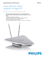
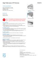
High Performance DTV Antenna - manual
 |
UPC - 719881171715
View all Maytag MFI2067AE manuals
Add to My Manuals
Save this manual to your list of manuals |
Page 2 highlights
High Performance DTV Antenna Technical specifications Maximum Gain VHF (Channels 2-13): 10dB Maximum Gain UHF(Channels 14-59): 15dB Noise Figure: < 4.0 aB Input Impedance: 75ohm Power 120V AC, 12V DC 100mA (UL listed) Accessories AC-DC Power Supply 5' RG-179 coax cable Silver Sensor TM Log Periodic UHF Element STOP Before You Start For this antenna to work properly, you must access the menu on the television you are connecting this antenna to (consult your television owner's manual) then set it to receive the signal from an ANTENNA instead of CABLE or SATELLITE. Connect/Install 1. Connect the supplied coaxial cable (attached to the back of the antenna) to the back of your TV. 2. Connect the power transformer to the antenna then to an AC power outlet. 3. Locate the signal source - Face the antenna towards the source of the signal (trnsmitter). Fo help locating the signal source go to www.antennaweb.org For VHF reception 1) For VHF reception, position the dipoles so that they are BOTH fully extended and straight up in the air perpendicular to the antenna 2) For channels 2 through 6, extend the dipoles fully and adjust to a horizontal position**. For channels,7 through 13, shorten the dipoles by 1/3 length and position in a "V" **. For FM reception 1) Extend the dipoles to 30" and position them either straight up or horizontally**. For UHF reception 1) Make sure the dipoles are collapsed and folded back underneath the antenna 2) For channels 14 through 69, rotate or point the center portion of the antenna ( large silver portion) towards the transmitter**. **Indicates that for best results - some adjustments may be necessary Using the amplifier NOTE: It is recommended that you try to obtain clear reception first ( with out the use of the amplifier) - if a clear picture is nto achieved then proceed to the steps below. 1) Make sure that you have the antenna adjusted to receive the clearest picture possible before you adjust the gain. 2) Slowly increase the amplifier gain until you achieve the clearest picture possible. Rarely, it is necessary to use maximum gain.Too much gain may result in overamplification or poor picture quality. NOTE: the amplfier gain can increased by rotating the knob located on the back of the antenna.The level of amplification is indicated by the size of the black arrow bext to the knob. Adjustable Gain Amplifier Hide-Away VHF Dipoles PHDTV3 UPC: 0 26616 01726 3 Date of issue Specifications are subject to change without notice. © 2004 Philips Accessories and Computer Peripherals North America All rights reserved. 1881 Route 46 West, Ledgewood, NJ 07852 Tel: 973-471-9050 • 800-526-7452 • Fax: 973-574-7210 • 800-471-3618 www.philips.com
-
 1
1 -
 2
2
 |
 |
